Alignments
EN 27LGE PDP 8.
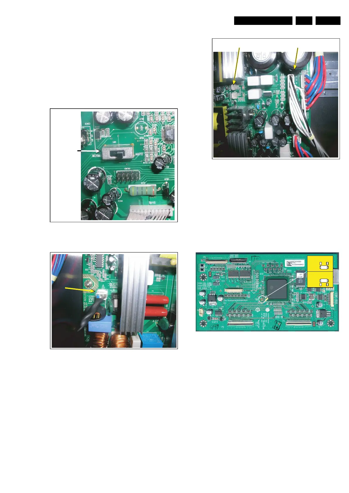
Vs Alignment on PSU
This describes the Vs alignment on the PSU:
1. Set the switch on the PSU to “AUTO”.
2. Connect Mains/AC Power (from Mains Filter) to the PSU
board (CN1308).
3. Connect a multimeter between CN06-Vs and ground (e.g.
frame).
4. Align Vs with the upper potmeter (VR501) to:
– 184 V for the PDP42V7A062 and PDP42V7K062
models (different from label !).
– 187 V for the other V7 models (as printed on label).
5. Set the switch on the PSU back to “NORMAL”.
Figure 8-3 Switch setting (Vs alignment step 1)
Figure 8-4 Connect Mains (Vs alignment step 2)
Figure 8-5 Vs measure and alignment point (step 3 &4)
8.2.4 Internal Test Patterns
The CTRL board is capable of generating it’s own video test
patterns. There are two possibilities, both based on R406 and
R407:
• R406 is open and R407 is fitted (= standard setting): the
test pattern is a full black screen (very low light output).
• R406 is fitted and R407 is open (desolder R407 and mount
it on pos. R406): the test patterns are shown in an
automatic loop.
Figure 8-6 Internal test pattern mode
Switch on PSU
F_15590_116.eps
120705
F_15590_117.eps
120705
F_15590_118.eps
120705
CN06-Vs
VR501
F_15590_114.eps
080705
R406
R407
R406
R407
Pattern loop
Black pattern
 Loading...