Service Modes, Error Codes, and Fault Finding
EN 15LGE PDP 5.
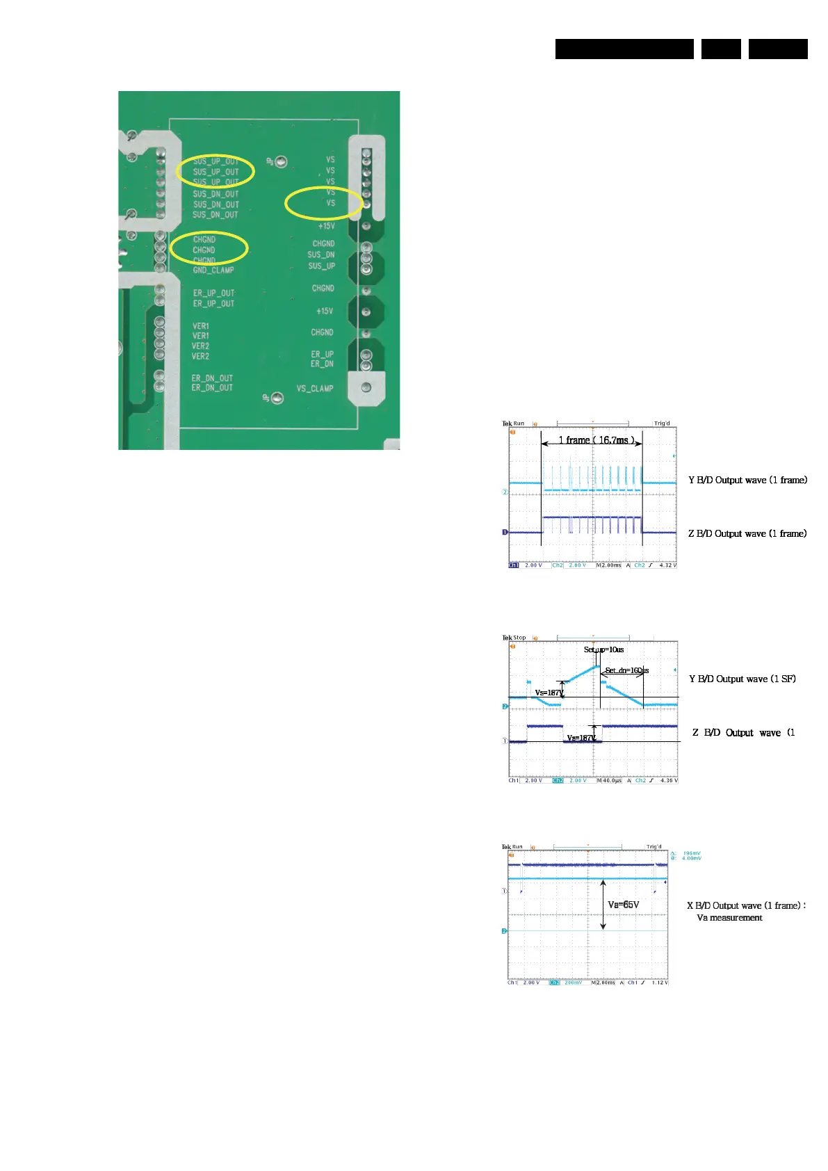
Figure 5-27 IPM check
5.2 Detailed Module Check PDP42V7*
5.2.1 No Display
The Screen Does Not Display a Picture
1. Check whether on the CTRL board LED (D1, D2, D3, D4,
and D5) is turned "on" or not.
2. Check the power and signal cable of the CTRL board.
3. Check if the X, Y, and Z boards are plugged in correctly.
4. Check the connection of the X, Y, and Z boards to the
CTRL board.
5. Measure the output wave of X, Y, and Z boards with an
oscilloscope (> 200 MHz) and find the trouble board by
comparing the output wave with below figure.
– Measure point for Y board: Bead B39.
– Measure point for Z board: Bead B28.
– Measure point for X board: P3.
6. Check the SCAN (Y side) IC.
7. Check the DATA (X side) TCP IC.
8. Replace the CTRL board.
9. Check if the fuse of Y and/or Z board is open and replace
when open.
10. Check the input voltage (Vcc= 5 V, Va= 65 V, Vs= 187 V).
Figure 5-28 Y and Z board output waveform (1 Frame)
Figure 5-29 Y and Z board output waveform (1 Sub Frame)
Figure 5-30 X board output waveform (1 Frame)
F_15590_095.eps
060705
<
?
<
F_15590_005.eps
060605
F_15590_006.eps
060605
<
<
SF)
F_15590_007.eps
060605
<
 Loading...