Mechanical Instructions
EN 20 Q552.2L LA4.
2012-Mar-16
back to
div. table
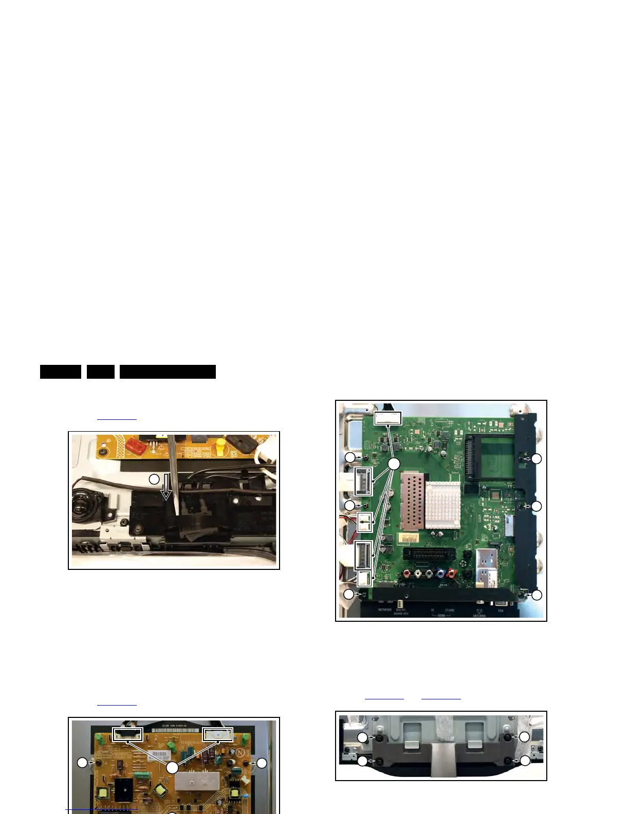
4.4.3 Mains Switch
Refer to Figure 4-17
for details.
Figure 4-17 Mains switch
The mains switch is mounted on a plastic subframe and can be
removed without removing the subframe.
1. Use a screwdriver and push the switch out of its casing [1].
2. Unplug the connectors.
When defective, replace the whole unit.
4.4.4 Main Power Supply
Refer to Figure 4-18
for details.
Figure 4-18 Main Power Supply
1. Unplug all connectors [1].
2. Remove the fixation screws [2].
3. Take the board out.
When defective, replace the whole unit.
4.4.5 Small Signal Board (SSB)
Refer to Figure 4-19
for details.
1. Unplug all connectors [1].
2. Remove the fixation screws [2].
3. Take the board out.
When remounting, ensure that the side shielding is positioned
correctly.
Figure 4-19 SSB
4.4.6 Keyboard Control, IR & LED Board
Refer to Figure 4-20
and Figure 4-21 for details.
Figure 4-20 Keyboard control, IR & LED board [1/2]
Figure 4-21 Keyboard control, IR & LED board [2/2]
1. Remove the stand [1].
2. Remove the stand subframe [2].
3. Remove the screws [3], unplug the connector and take the
board out.
When defective, replace the whole unit.