Circuit Descriptions
EN 57Q552.2L LA 7.
2012-Mar-16
back to
div. table
Figure 7-5 DC/DC converters
7.4 Front-End Analogue and DVB-T, DVB-C;
ISDB-T reception
7.4.1 Brazil region
The Front-End for the Brazil region consist of the following key
components:
• Hybrid Tuner with integrated SAW filter and amplifier
• External ISDB-T channel decoder covering the Brazilian
digital terrestrial TV standard
• Bandpass filter
• Amplifier
• PNX85500 SoC TV with integrated analogue demodulator.
Below find a block diagram of the front-end application for this
region.
Figure 7-6 Front-End block diagram Brazil region
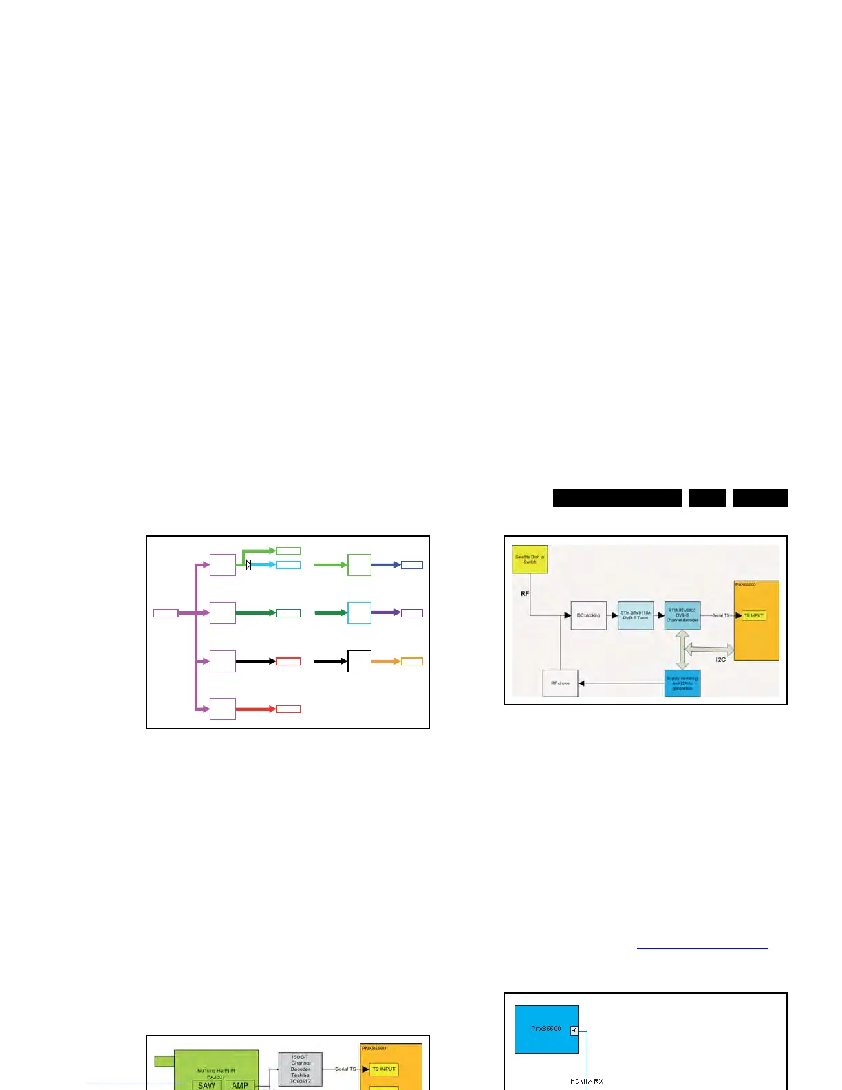
7.5 Front-End DVB-S(2) reception
The Front-End for the DVB-S(2) application consist of the
following key components:
• Satellite Tuner; I
2
C address 0xC6 (bridged via channel
decoder)
• Channel decoder; I
2
C address 0xD0
• LNB switching regulator; I
2
C address 0x14
• Amplifier
• PNX855xx SoC TV processor with integrated DVB-T and
DVB-C channel decoder and analogue demodulator.
Below find a block diagram of the front-end application for
DVB-S(2) reception.
Figure 7-7 Front-End block diagram DVB-S(2) reception
This application supports the following protocols:
• Polarization selection via supply voltage (18V = horizontal,
13V = vertical)
• Band selection via “toneburst” (22 kHz): tone “on” = “high”
band, tone “off” = “low” band
• Satellite (LNB) selection via DiSEqC 1.0 protocol
• Reception of DVB-S (supporting QPSK encoded signals)
and DVB-S2 (supporting QPSK, 8PSK, 16APSK and
32APSK encoded signals), introducing LDPC low-density
parity check techniques.
7.6 HDMI
In this platform, the Silicon Image Sil9x87 HDMI multiplexer is
implemented. Refer to figure 7-8
HDMI input configuration for
the application.
Figure 7-8 HDMI input configuration
The following multiplexers can be used:
• Sil9187A (does not support “Instaport” technology for fast
switching between input signals)
• Sil9287B (supports “Instaport” technology for fast
switching between input signals).
The hardware default I
2
C addresses are:
• Sil9187A: 0xB0/0xB2 (random: software workaround)
• Sil9287B: 0xB2 (fixed).
The Sil9x87 has the following specifications:
• +5V detection mechanism
• Stable clock detection mechanism
• Integrated EDID