UM EN AXL F SYS DIAG
8
PHOENIX CONTACT 8663_en_03
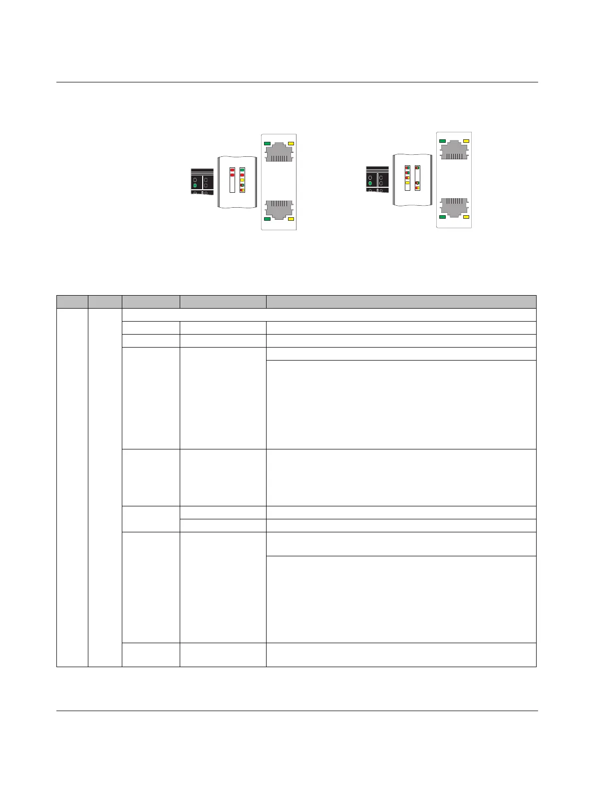
1.1.1 Indicators D and E on controllers and bus couplers
Figure 1-1 Indicators on controllers and bus couplers
Example: AXC 1050 Example: AXL F BK EIP
LNK ACT
LNK ACT
UL
BF
SF
RUN
D
E
FAIL
DBG
LNK ACT
LNK ACT
UL
NET
MOD
CO
RDY
D
E
PP
Tabelle 2 Indicators on controllers and bus couplers
Des. Color Meaning State Description
DRed/
yellow/
green
Diagnostics for local bus communication
Power off Off The station coupler is in (power) reset.
Ready Yellow on The station is ready for operation, no data exchange taking place.
Ready + Bus
error
Flashing red Local bus error on startup
Possible causes:
– Configuration cannot be generated, information is missing from
a device
– Chip version of a device is <V1.1
– The desired and actual configuration are different
– No local bus device connected
– The maximum number of local bus devices is exceeded.
Active Flashing green The station is ready for operation, communication within the station
is OK.
The data is not valid. Valid data from the controller/higher-level net-
work is not available.
There is no fault in the module.
Active +
Force
Flashing yellow Access from Startup+ in I/O check mode
Flashing yellow/red Local bus error during active I/O check
Active +
Bus error
Red on The station is ready for operation but has lost connection to at least
one device.
Possible causes:
– Communication error
– Local bus device has been removed or configured device is
missing.
– Reset at a local bus device
– Serious device error at a local bus device (local bus device can
no longer be accessed)
Run Green on The bus coupler is ready for operation, communication within the
station is OK. All data is valid. There are no faults.
 Loading...