Diagnostics in the Axioline F system
8663_en_03 PHOENIX CONTACT 9
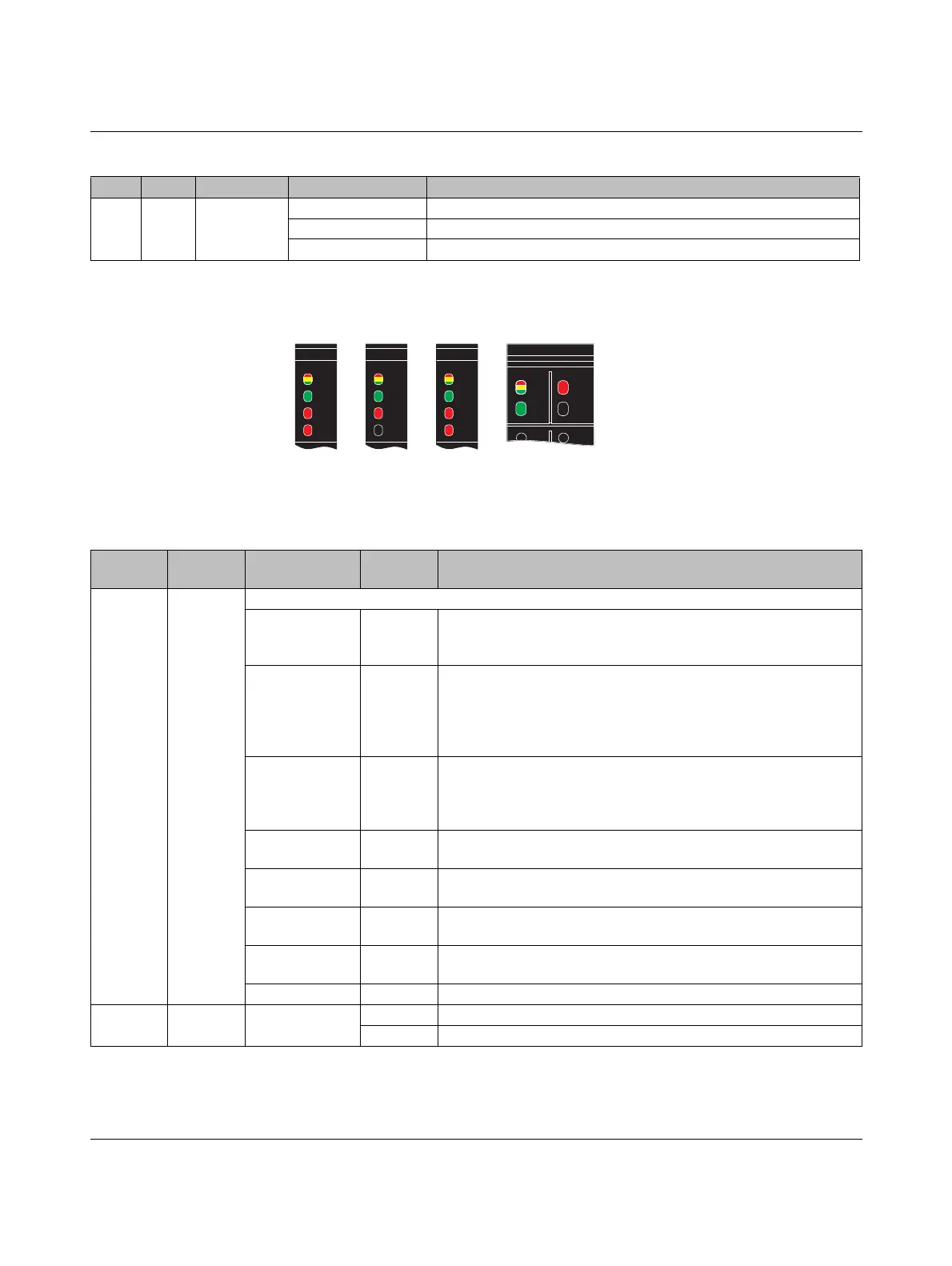
1.1.2 Indicators D and E on I/O modules
Figure 1-3 LEDs D and E on the power connectors of the I/O modules
(examples)
E Yellow/
red
Error Yellow on I/O warning at a local bus device.
Red on I/O error at a local bus device.
Off No I/O messages present.
Tabelle 2 Indicators on controllers and bus couplers
Des. Color Meaning State Description
Tabelle 4 LEDs D and E on the power connectors of the I/O modules
Designa-
tion
Color Meaning State Description
D Red/yel-
low/green
Diagnostics for local bus communication
Run Green on The device is ready for operation, communication within the station
is OK.
All data is valid. There are no faults.
Active Flashing
green
The device is ready for operation, communication within the station
is OK.
The data is not valid. Valid data from the controller/higher-level net-
work is not available.
There is no fault in the module.
Device applica-
tion not active
Flashing
green/yel-
low
The device is ready for operation, communication within the station
is OK.
Output data cannot be output and/or input data cannot be read.
There is a fault on the I/O side of the module.
Ready Yellow on The device is ready for operation but has still not detected a valid
cycle after power-on.
Connected Flashing
yellow
The device is not (yet) part of the active configuration.
Reset Red on The device is ready for operation but has lost the connection to the
bus head.
Not connected Flashing
red
The device is ready for operation but there is no connection to the
previously existing device.
Power down Off Device is in (power) reset.
E1/E2 Red Error On Error, see module-specific documentation.
Off No error.
 Loading...