ManualAVM
TM
2Page 18/24
Operation
5.6 Setting the vacuum-signal level
With AVM™2 it is easy to set a suitable vacuum-
signal level for the system. It is possible to set up to
16 different combinations of vacuum levels, from
position 0 to F according to the table below
(clockwise).
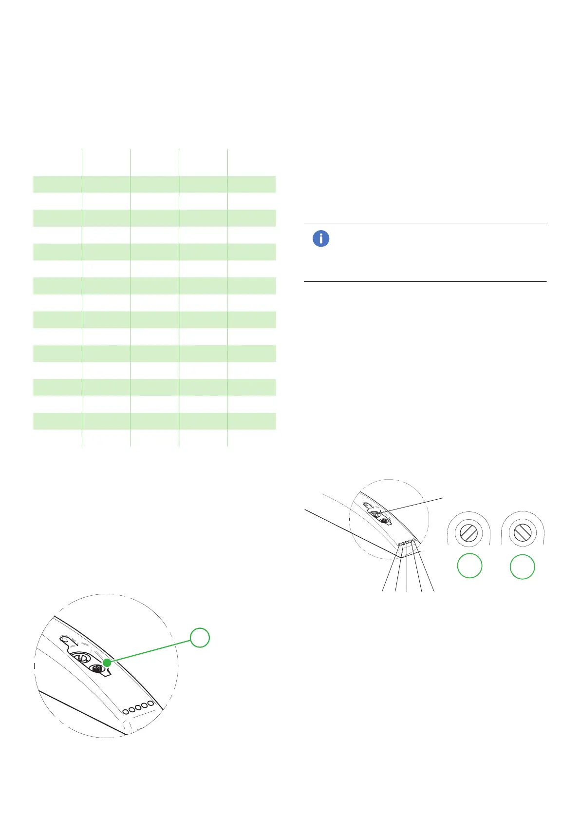
Pos
-kPa
S1 S2
-inHg
S1 S2
0 20 40 6 12
1 20 50 6 15
2 20 60 6 18
3 30 45 9 13
4 30 50 9 15
5 30 60 9 18
6 30 70 9 21
7 40 55 12 16
8 40 60 12 18)*
9 40 70 12 21
A 40 80 12 24
B 50 65 15 19
C 50 70 15 21
D 50 80 15 24
E 60 75 18 22
F 60 80 18 24
)* Default setting.
In order to set a suitable vacuum-signal level you
should turn the rotary switch (also possible during
operation) located under the protection lid in the
upper cover. The display shows the lower vacuum-
signal level (S1) and shortly afterwards the upper
vacuum-signal level (S2), and after this it switches
once between the selected levels as a confirmation.
After a short while the display returns to showing the
actual vacuum level.
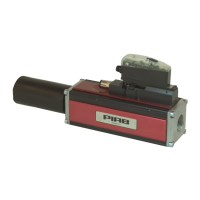
1
1: Rotary switch.
5.7 Changing the units in the display
The default setting for the AVM™2 is -kPa. In order
to switch to showing the vacuum signal levels in
-inHg, you should press the ES button and keep it
depressed for more than 3 seconds. Choose unit by
pressing the ES button again within 3 seconds. The
display shows PA for -kPa and HG for -inHg. After a
short while the display returns to showing the actual
vacuum level.
5.8 LED status indicators
S1 and S2 (green light)
The LED (2) indicates when the preset vacuum signal
levels for S1 and S2 have been reached.
Note!
S1 is recommended to use as Go/No Go (ok/
not ok) signal for the vacuum system. S2 is
an indicator that ES level has been reached.
V1 and V2 (red light)
The LED indicates that valve V1 is open or closed,
vacuum generation activated or not.
The LED indicates that valve V2 is open, blow-off
activated.
ES (yellow light)
The LED indicates that the energy-saving function is
activated. Can be controlled from pin 8 or manually
by ES on/off button above M12 connector
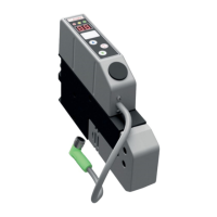
Setting blow-off power
The flow rate (power) from the blow-off is infinitely
variable by a blow-off adjustment valve (V3).
V3
V1 V2 ES S1 S2
1
2
Figure 19 1: Fully open, 2: Closed.