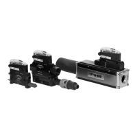
ManualAVM
TM
2Page 11/24
Installation
4. Installation
AVM™2 can be installed in any orientation. Ensure
that the exhaust (3) from the ejector is not blocked.
When connecting supply air (1) and vacuum hoses (2)
to the unit, it is important to choose proper pipe
dimensions to prevent pressure drops. Avoid
restrictive inner diameters, long piping distances,
sharp bends and smallsized connections.
4.1 Unpacking
When unpacking check that the product is complete
and undamaged. The manual should be stored for
future reference.
Warning!
Do not install or operate your product if it is
damaged during transport, handling or use.
Damage may result in bursting and cause
injury or property damage.
4.2 Pneumatic Installation
Warning!
•
Do not install the product in a fully closed
compartment, without ventilation and
exhaust channelling.
•
Do not use the product if the compressed
air line is not properly secured.
Note!
The quality of the compressed air shall fulfil
the requirements in DIN ISO 8573-1 class 4.
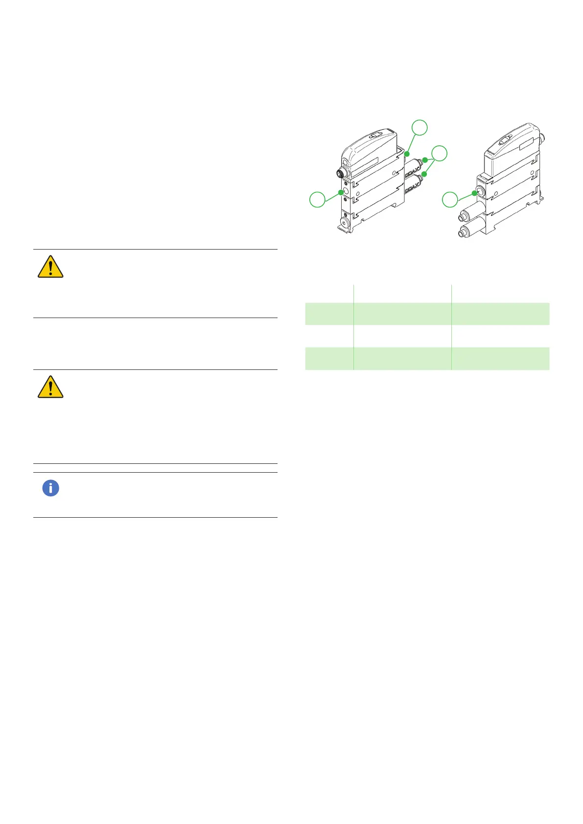
4.2.1 P3010 AVM™2
1
2
3
2
Figure 6 P3010 AVM
TM
2
Position Description Note
1 Compressed air G1/8”, Ø6mm
2 Vacuum Ø10mm, 1/4” NPSF
3 Exhaust Ø8mm