ManualAVM
TM
2Page 13/24
Installation
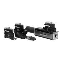
4.2.3 P6010 AVM™2
2
2
4
1
1
3
3
A
B
1
1
2
2
3
3
4
Figure 8 A: standard version, B: with separated blow-off
Position Description Note
1 Compressed air G1/4”, Ø10mm
2 Vacuum G1”, G3/4”, 1” NPSF, 3/4” NPSF
3 Exhaust G1/4”, Ø10mm
4 Separate blow-off (compressed air) G1/4”, Ø10mm
For more detailed information see the dimensional drawing.
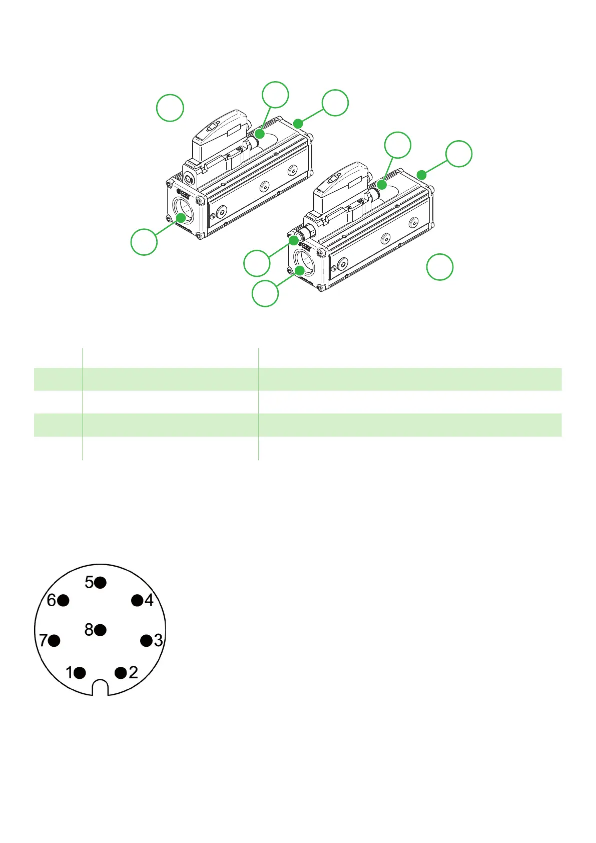
4.3 Electrical connection
4.3.1 pin configuration
Figure 9 M12-8 pin connector.