Do you have a question about the Pilz PNOZ ms1p and is the answer not in the manual?
Specifies the validity period and updates for the documentation.
Instructions on how to use this operating manual for installation and commissioning.
Defines warning symbols (DANGER, WARNING, CAUTION, NOTICE) and informational symbols.
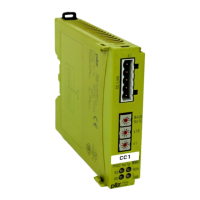
Details the expansion module PNOZ ms1p and its jumper.
Lists monitoring capabilities, measured variables, and connection technologies.
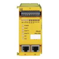
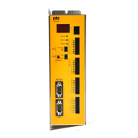
Illustrates the device's front panel, connectors, and status LEDs.
Describes the module's purpose, standards (EN ISO 13849-1, EN IEC 62061), and application areas.
Refers to documentation for compatible base unit and PNOZmulti Configurator versions.
Covers safety regulations, assessment needs, and qualified personnel.
Outlines conditions that invalidate warranty and liability claims.
Advises compliance with local regulations for electronic device disposal.
Lists essential safety measures for safe operation and maintenance.
Details the relay's redundancy and self-monitoring safety criteria.
Explains how the speed monitor monitors axes and transfers status to the base unit.
Illustrates the connectivity of inputs, outputs, and modules within the system.
Details the types of input devices compatible with the system.
Specifies requirements and connection details for proximity switches.
Details requirements and connection options for incremental encoders.
Describes configuring a proximity switch and encoder on a single axis for increased availability.
Covers cabinet installation, mounting rail, ambient temperature, and EMC requirements.
Details connecting modules, fitting the terminator, and maximum expansion limits.
Provides physical dimensions of the unit and its mounting.
Explains wiring based on PNOZmulti Configurator, technical details, and wire specifications.
Details the pinout for the 8-pin RJ45 connector used for incremental encoders.
Provides instructions for connecting proximity switches to axes and the 0V terminal.
Explains connecting encoders via adapter or directly, axis mapping, and cable use.
Describes connecting proximity switches and encoders to axes.
Illustrates various wiring configurations for proximity switches and encoders.
Describes initial system messages and the status of base unit and PNOZ ms1p LEDs.
Explains display elements and how to diagnose device status.
Details signal statuses for standstill, faults, and rotating shafts based on inputs.
Describes potential malfunctions, such as incorrect direction of rotation signals.
Lists supply voltage, power consumption, input signal levels, and frequency ranges.
Specifies number of inputs, signal levels, resistance, and frequency range for proximity switches.
Details number of inputs, connection type, supply voltage, and signal levels for encoders.
Covers switch-off delay, de-energisation interruption, and reaction times.
Details ambient and storage temperature, humidity, EMC, vibration, and shock stress.
Covers mounting position, dimensions, materials, and conductor cross-section for terminals.
Provides safety data (PL, SIL CL, PFD, PFHD) for initiator and incremental encoder inputs.
Lists the product type, features, and order number for the PNOZ ms1p.
Details order numbers for connection terminals, terminators, and jumpers.
Illustrates a configuration for safe standstill monitoring using the PNOZmulti Configurator.
Demonstrates safe monitoring with a 'reduced speed' operating mode configuration.
| Brand | Pilz |
|---|---|
| Model | PNOZ ms1p |
| Category | Control Systems |
| Language | English |