PNOZ s11
Operating Manual PNOZ s11
21693-EN-11
| 9
Function description
with PNOZsigma base unit:
} Dual-channel operation via PNOZsigma connector
without PNOZsigma base unit:
} Single-channel operation: one input circuit affects the output relays
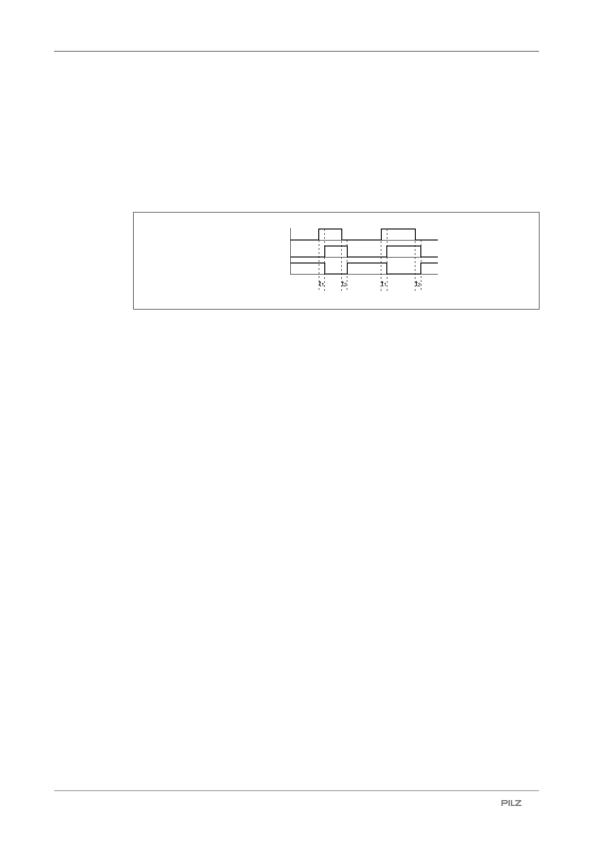
Timing diagram
POWER/Input
Output safe
Output aux.
Legend
} POWER/Input: Supply voltage/input circuit
} Output safe: Safety contacts
} Output aux.: Auxiliary contacts
} t
1
: Switch-on delay
} t
2
: Delay-on de-energisation
Installation
Install contact expansion module without base unit:
} Ensure that the plug terminator is inserted at the side of the unit.
Connect base unit and PNOZsigma contact expansion module:
} Remove the plug terminator at the side of the base unit and at the contact expander mod-
ule
} Connect the base unit and the contact expansion module using the connector supplied,
before mounting the units to the DIN rail.
Control cabinet installation
} The safety relay should be installed in a control cabinet with a protection type of at least
IP54.
} Use the notch on the rear of the unit to attach it to a DIN rail (35 mm).
} When installed vertically: Secure the unit by using a fixing element (e.g. retaining bracket
or end angle).
} Push the unit upwards or downwards before lifting it from the DIN rail.

 Loading...


