PNOZ s9
Operating Manual PNOZ s9
21401-EN-10
16
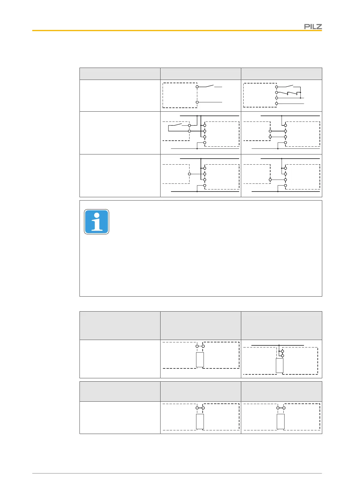
} 1-channel input circuit/feedback loop
Input circuit Input circuit Feedback loop
Without base unit (stand-
alone)
A1
A2
24 V DC
0 V
PNOZs9
S34
S32
K5
K6
S3
Base unit:
Safety relay PNOZ X
24 V DC
0 V
A1
A2
PNOZs9
S32
S34
PNOZ X
24 V DC
0 V
A2
PNOZs9
45
46
PNOZ X
S34
feedback
loop
Base unit:
Safety relay PNOZelog;
driven via semiconductor
outputs (24 VDC)
24 V DC
0 V
A1
A2
PNOZs9
S32
S34
PNOZelog
Output
24 V DC
0 V
A2
PNOZs9
45
46
PNOZelog
S34
*
feedback
loop
INFORMATION
Feedback loop
The inputs that evaluate the feedback loop will depend on the base unit and
application.
* with PNOZelog as base unit:
The selectable delay-on de-energisation of PNOZ s9 may only be used with
the safety relay PNOZ e1p. Other PNOZelog safety relays must be oper-
ated without delay-on de-energisation.
} 2-channel input circuit
Base unit: Safety relays
PNOZ s3, PNOZ s4, PNOZ
s5
Base unit: Safety relays
PNOZ s1, PNOZ s2
The input circuit is connec-
ted and evaluated via the
connector.
Interface
PNOZsigma
PNOZ s3
PNOZ s4
PNOZ s5
PNOZ s9
S34
S11
Interface
PNOZsigma
PNOZ s1
PNOZ s2
PNOZ s9
A1
24 V DC
S34
Base unit: Two-hand con-
trol device PNOZ s6
Base unit: Two-hand con-
trol device PNOZ s6.1
The input circuit is connec-
ted and evaluated via the
connector.
Interface
PNOZsigma
PNOZ s6
PNOZ s9
S34
S12
Interface
PNOZsigma
PNOZ s6.1
PNOZ s9
S34
S24

 Loading...