PNOZ X2.5P
Operating Manual PNOZ X2.5P
20407-EN-10
9
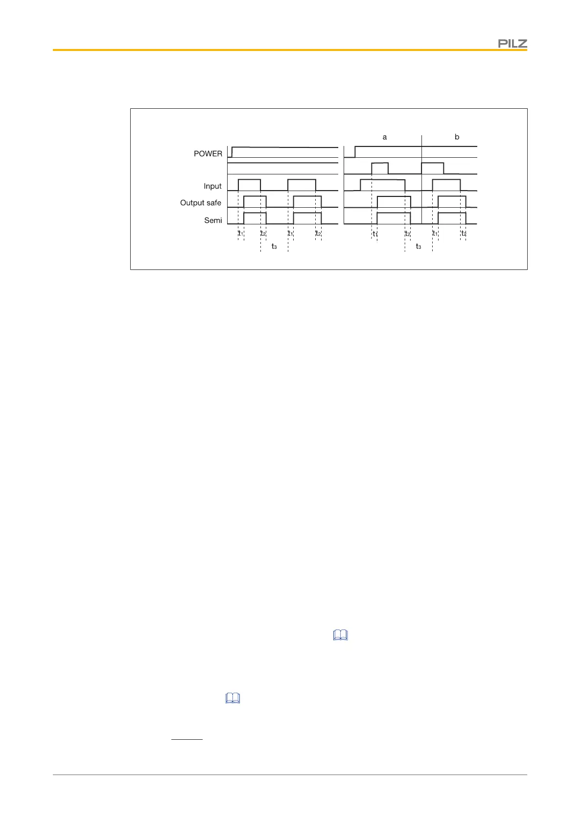
Timing diagram
Legend
} Power: Supply voltage
} Start: Start circuit
} Input: Input circuit
} Output safe: Safety contacts
} Semi: Semiconductor output
} [1]: Automatic start
} [2]: Manual start
} a: Input circuit closes before start circuit
} b: Start circuit closes before input circuit
} t
1
: Switch-on delay
} t
2
: Delay-on de-energisation
} t
3
: Recovery time
Installation
} The unit should be installed in a control cabinet with a protection type of at least IP54.
} Use the notch on the rear of the unit to attach it to a DIN rail (35 mm).
} When installed vertically: Secure the unit by using a fixing element (e.g. retaining
bracket or end angle).
Wiring
Please note:
} Information given in the "Technical details [ 14]" must be followed.
} Outputs 23-24, 33-34 are safety contacts.
} Semiconductor output Y11-Y12 shouldnot be used for safety circuits!
} To prevent contact welding, a fuse should be connected before the output contacts (see
Technical details [ 14]).
} Calculation of the max. cable length l
max
in the input circuit:
 Loading...