PSEN sl-0.5n 1.1
Operating Manual PSEN sl-0.5n 1.1
22173-EN-05
19
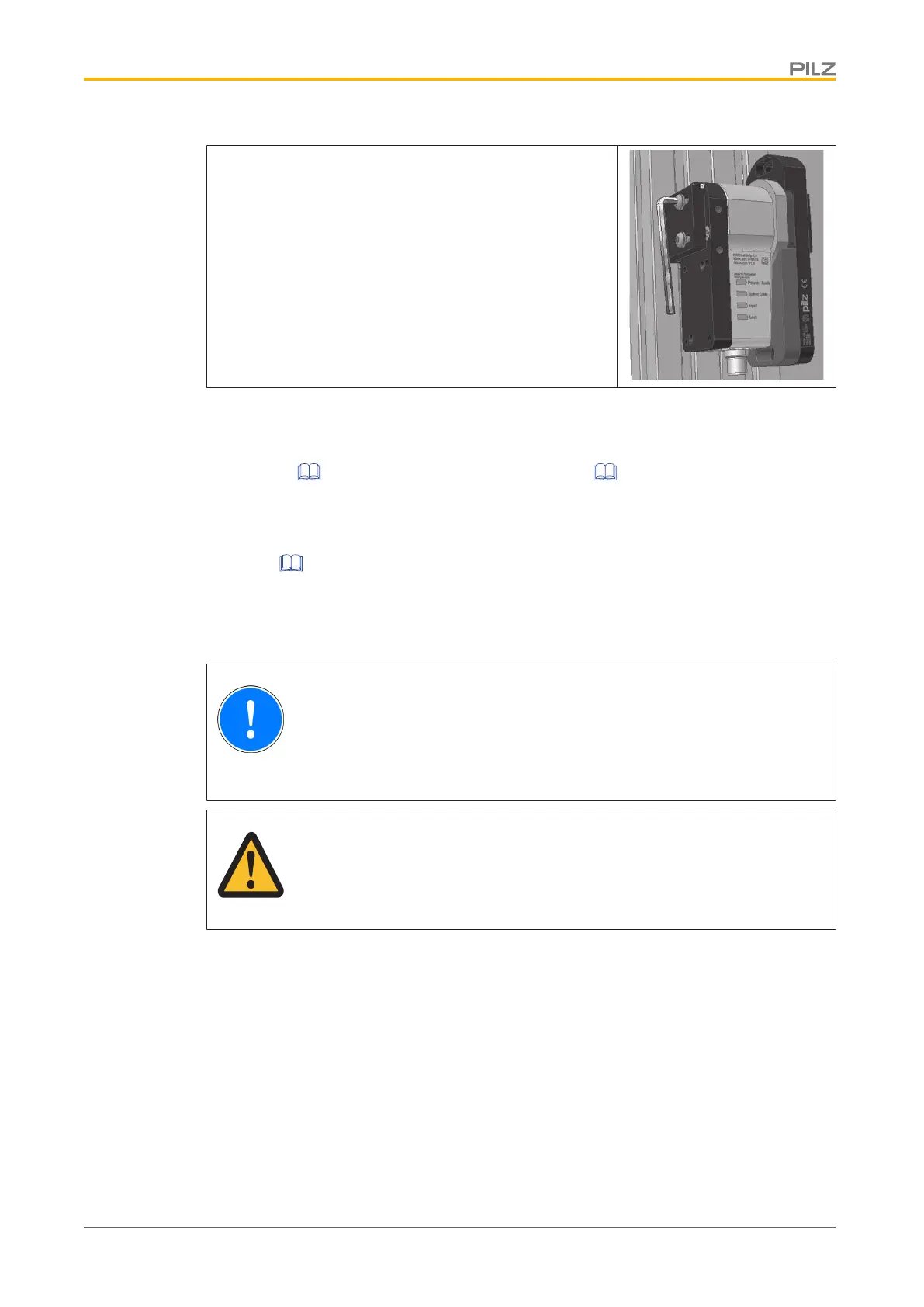
Align the safety switch to the actuator and tighten the
screws.
Adjustment
} The stated operating distances (see Technical details: System with normal
actuator [ 23], System with free-moving actuator [ 27]) only apply when the
safety switch and actuator are installed facing each other in parallel. Operating dis-
tances may deviate if other arrangements are used.
} Note the maximum permitted lateral and vertical offset (see Lateral and vertical
offset [ 10]).
Operation
NOTICE
The safety function should be checked after initial commissioning and each
time the plant/machine is changed. The safety functions may only be
checked by qualified personnel.
CAUTION!
Contaminated surfaces can reduce the holding force of the electromagnet.
Make sure that the contact surfaces are clean.
Status indicators:
} "Power / Fault" LED illuminates green: The unit is ready for operation
} "Safety Gate" LED lights up yellow: Actuator is within the response range
} "Lock" LED lights up green: Magnetic guard locking device active
} "Input" LED lights up yellow: The unit is ready for operation
Error display through periodic flashing:
} "Power/Fault" LED lights up red: Error message
Flashing codes for fault diagnostics are output to the "Safety Gate" or "Input" LED (see
Error display through flashing codes).
Remedy: Rectify fault and interrupt power supply.

 Loading...


