Do you have a question about the Pilz PNOZ m B0 and is the answer not in the manual?
Specifies the period for which the product documentation is valid.
Provides guidance on how to effectively read and use the manual for installation and commissioning.
Explains warning symbols (DANGER, WARNING, CAUTION, NOTICE) and their meanings.
Details the base unit PNOZ m B0, terminator, and documentation media.
Lists key features like configurable I/Os, semiconductor outputs, and input capabilities.
Explains the necessity and types of chip cards for product operation and configuration.
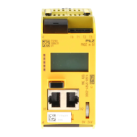
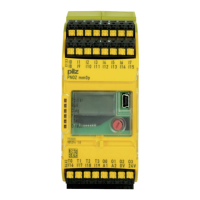
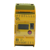
Illustrates the physical layout of the PNOZ m B0 unit, including ports and LEDs.
Defines the product's application scope and compliance with relevant safety standards.
Refers to specific software versions required for product configuration.
Outlines the need for safety assessment and adherence to regulations.
Specifies that only trained and competent persons should handle the product.
Details conditions under which warranty and liability claims are invalidated.
Provides guidance on environmentally sound disposal of the electronic device.
Advises consulting other specific manuals for advanced functions and safety procedures.
Describes the built-in safety features like redundancy and self-monitoring.
Explains how inputs/outputs operate based on safety circuits configured via software.
Refers to external documentation for details on system reaction time calculations.
Presents a visual overview of the product's internal connectivity and components.
Details how to access and interpret status and error messages via LEDs and software.
Provides instructions for installing the unit within a control cabinet, including environmental compliance.
Specifies required clearances for proper heat dissipation and ventilation.
Lists the physical dimensions of the base unit, including depth, height, and width.
Step-by-step guide for installing the base unit without additional modules.
Instructions for linking expansion modules to the base unit using jumpers and terminators.
Outlines best practices and rules for wiring the system components correctly.
Covers the procedure for wiring inputs/outputs and connecting the power supply.
Illustrates different power supply connection methods for the control system and outputs.
Steps to transfer the safety project from a chip card to the base unit.
Procedure for downloading the safety project using a computer via USB.
Emphasizes the critical need to test safety devices after configuration changes.
Guidelines for handling, protecting, and inserting the chip card to prevent damage.
Provides a detailed wiring diagram for a dual-channel E-STOP and safety gate setup.
Explains the status indicated by the POWER, RUN, and other LEDs on the base unit.
Details the information displayed on the LC screen and menu navigation.
Describes the operation of the rotary knob for setting parameters and navigating menus.
Illustrates the schematic flow for navigating through the device's menu functions.
Guides on how to view error messages on the LC display when errors do not cause a safe condition.
Explains how to read and interpret the error stack for fault diagnostics.
Covers product certifications, application range, and device code.
Provides specifications for supply voltage, current, and power dissipation.
Details technical specifications for configurable inputs and auxiliary outputs.
Lists technical parameters for the device's semiconductor outputs.
Provides technical data for the test pulse output functionality.
Specifies timing parameters like simultaneity in two-hand circuits and processing time.
Details operating and storage temperatures, humidity, EMC, and pollution degree.
Covers mounting type, dimensions, weight, and cable length specifications.
Presents SIL and PL ratings for various unit configurations and safety functions.
Describes interface classification and compatible parameters for dynamic testing.
Graph showing the relationship between capacitive load and current for semiconductor outputs.
Graph illustrating the total current limits for semiconductor outputs based on load.
Graphs detailing relative humidity limits for operation and storage conditions.
Lists the main product (PNOZ m B0) and its associated order number.
Provides order numbers for essential accessories like terminators, cables, and terminals.
Lists international contact numbers and email for Pilz technical assistance.
| Product type designation | PNOZ m B0 |
|---|---|
| Type | Base unit |
| Number of safe inputs | 20 |
| Number of test pulse outputs | 4 |
| Supply voltage | 24 V DC |
| Configurable | Yes |
| Connection type | Screw terminals |
| PL | PL e |
| Category | 4 |
| Storage temperature range | -25 - 70 °C |
| Protection class | IP20 |
| Width | 45 mm |
| Depth | 121 mm |
| SIL | SIL 3 |
| Operating temperature range | -20 - 60 °C |
| Standards | EN ISO 13849-1, EN 62061 |
