Commissioning
Operating Manual PNOZ m B0
1002660-EN-07
22
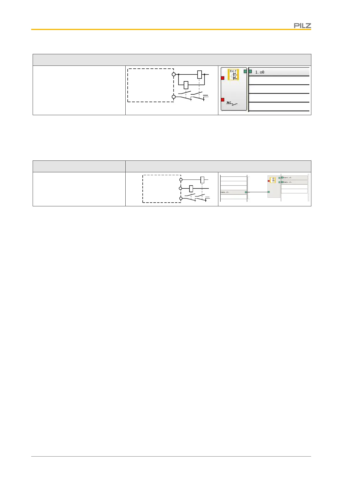
Semiconductor outputs
Single output with advanced fault
detection*
*Two loads may be connected to each safety output with advanced fault detection, even on
applications in accordance with EN IEC 62061, SIL CL 3. Prerequisite: Feedback loop is
connected, shorts across contacts and external power sources are excluded (e.g. through
separate multicore cables). Please note that, in the event of an error in the feedback loop,
the safety system switches to a safe condition and shuts down all the outputs.
Feedback loop Redundant output
Contacts from external contactors
K1
L+
L-
K2
O0 (O2)
O1 (O3)
IM0
L-
6.2.2 Load project from chip card
Procedure:
} Insert the chip card containing the current project into the card slot on the base unit.
} Switch on the supply voltage. The LC display shows the project name, CRC sum and
the date the project was created. Please check this information.
} Load the project by pressing the rotary knob. For the project to be downloaded, the
rotary knob must be held down for between 3 and 8 seconds. Once the project has
been successfully downloaded, the status of the inputs and outputs will be shown on
the display.
6.2.3 Load project via USB port
Procedure:
} Insert a chip card into the card slot on the base unit.
} Connect the computer containing the PNOZmulti Configurator to the base unit via the
USB port.
} Switch on the supply voltage.
} Download the project (see PNOZmulti Configurator's online help).
} Once the project has been successfully downloaded, the status of the inputs and out-
puts and the supply voltage will be shown on the display. The "RUN" LED will be lit.

 Loading...


