Installation
Operating Manual PNOZ m B0
1002660-EN-07
18
5.4 Connecting the base unit and expansion modules
The position of the expansion modules is defined in the PNOZmulti Configurator. The ex-
pansion modules are connected to the left or right of the base unit, depending on the type.
Please refer to the document "PNOZmulti System Expansion" for details of the number of
modules that can be connected to the base unit and the module types.
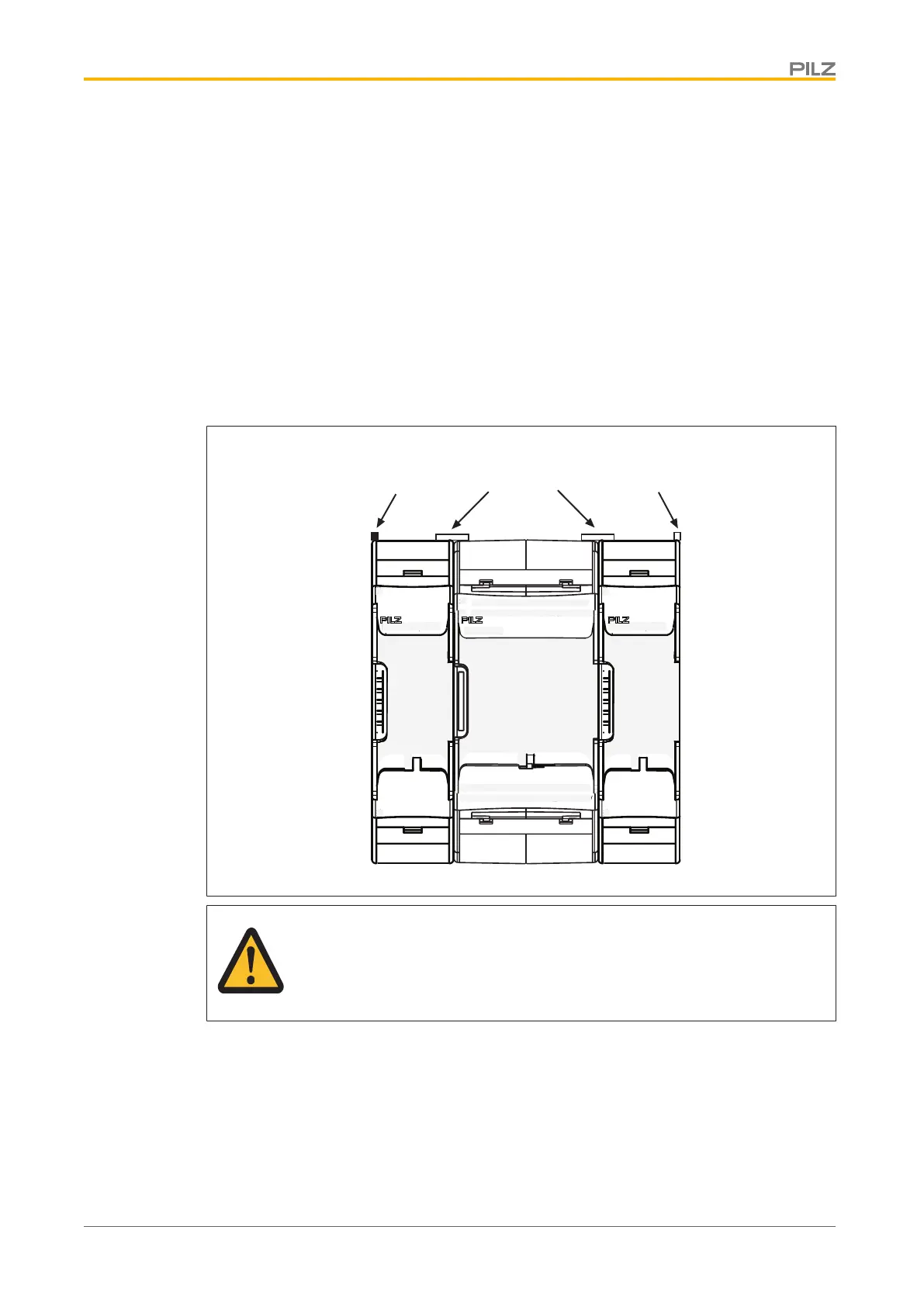
The modules are linked via jumpers.
} Remove the terminator on the side of the base unit and on the expansion module.
} Install the base unit and expansion modules on the mounting rail in the order configured
in the PNOZmulti Configurator and connect the units using the jumper supplied.
} Fit the terminator to the unconnected interfaces on the base unit and expansion mod-
ule.
Terminator
Jumper Terminator
CAUTION!
Only connect the base unit and expansion modules when the supply voltage
is switched off.

 Loading...


