Function description
Operating Manual PSENvip RL D P Set
1001641-EN-09
| 36
} 5
– The safety system reflects the tool class transmitted by the PSENvip.
– Tool class PLC -> PSENvip Bit 1/2 = 0 or 1, depending on the tool class
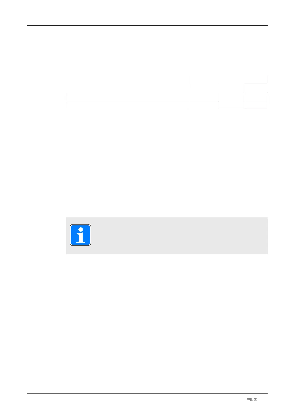
Tool class
1 2 3
Tool class PLC -> PSENvip Bit 1 0 1 1
Tool class PLC -> PSENvip Bit 2 1 0 1
} 6
The PSENvip ends communication.
All outputs are set = 0:
– Activate = 0
– Acknowledge PSENvip -> PLC = 0
– Tool class PSENvip -> PLC Bit 1 = 0
– Tool class PSENvip -> PLC Bit 2 = 0
} 7
– The safety system ends communication.
PLC Ready = 1/0 pulse edge
– Tool class PLC -> PSENvip Bit 1/2 = 0 or 1, depending on the original status
INFORMATION
The requirements of the user program in the safety system are described
under "System Connections".
4.5 Protected field modes
Four protected field modes are available for adapting to different bending functions:
} Full protected field: Standard press stroke
} Reduced protected field:
– Box bending press stroke
– Back gauge press stroke
– Box bending with back gauge press stroke
Use of the protected field modes depends on the tool class. Not all protected field modes
can be selected with tool class 2 and 3.


 To Next Page