PDP-502MX, PDP-502MXE
37
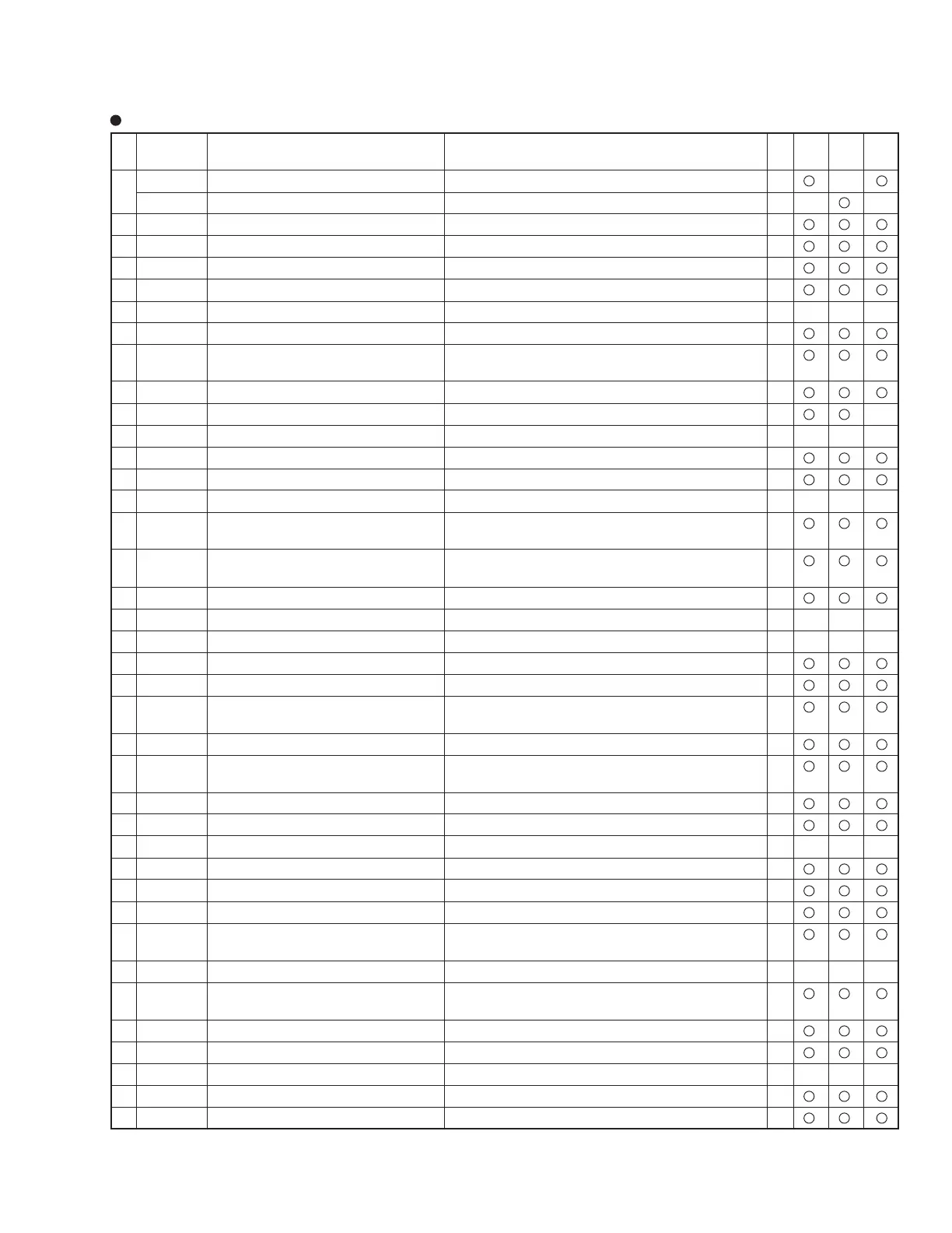
1 S2_DET S2 Signal detection 0–1.3V: Normal, 1.4–2.4V: Letter Box, 2.5–5V: Squeeze I ––
OPTION Option Video Box detection High: non existence, Low: existence of Video Box I –– ––
2 SCL I
2
C-BUS Clock 0–5V clock signal: always communicating when power on O
3 SDA I
2
C-BUS Data 0–5V clock signal: always communicating when power on I/O
4 V_DETI Result of Y signal detection High: Y Signal detected, Low: Y Signal not detected I
5 PN_BUSY BUSY signal from Panel U-Com High: In exchanging input functions, Low: Normal I
6 ––––– No allocation(not used)
7 CLK2 Clock output for Serial 3 lines 0–5V clock signal: always communicating when power on O
8 DATA2 Data output for Serial 3 lines 0–5V serial signal: always communicating when power on O
(both-way communication with Full Auto Zoom IC )
9 DTO_SU Serial data input from SYNC u-com High: Normal, 0–5V serial signal: During communication I
10 VOL Audio volume output PWM output O ––
11 ––––– No allocation (not used)
12 (E) SCL I
2
C-BUS Clock for E
2
PROM High: Normal, 0–5V clock signal: During communication I/O
13 (E) SDA I
2
C-BUS Data for E
2
PROM High: Normal, 0–5V serial signal: During communication I/O
14 CTS Not used
15 REQ_SU Request to read detected frequency from High: Normal, Low: In requesting I
SYNC u-com
16 *RST2 Reset Signal from SYNC u-com & Digital High: Normal, Low: In resetting I
Video Assy
17 EP_RST Reset output to E
2
PROM High: In resetting, Low: Normal O
18 BUSY2 Not used
19 SCL2 Not used
20 TXD RS-232C sending data 0–5V serial signal O
21 RXD RS-232C receiving data 0–5V serial signal I
22 REM Remote Control unit signal input High: Normal, 0–5V serial signal: In input from Remote I
Control unit
23 KEY Key Matrix, Key of the unit input High: Normal, 0–5V serial signal: In Key input I
24 CNVSS Controlling operation mode of u-com of Low: Normal I
the unit
25 *RST Reset input High: Normal, Low: In Reset I
26 POWER Power on/off High: When power on, Low: In Stand-by O
27 ––––– No allocation (not used)
28 X_IN Clock input 10 MHz sine wave I
29 X_OUT Clock output 10 MHz sine wave O
30 VSS Power supply terminal STB GND I
31 SC_DT
Detecting SYNC Signal output from Analog
High: existence of Sync signal, Low: non existence I
(ULK_PLL)
Assy to Digital Assy
32 RTS Not used
33 RMT Signal of request to quit sending Low: Normal I
commands from Panel u-com
34 PN_ERR
Communication error signal from Panel u-com
Low: Normal I
35 *PN_RST
Reset signal output to Panel u-com & IP u-com
High: Normal, Low: In Reset O
36 ––––– No allocation (not used)
37 *GRN Green LED lighting Low: In lighting Green LED O
38 *RED Red LED lighting Low: In lighting Red LED O
Pin Function
Pin
No.
Name Function
Operation of Terminals (during power on)
I/O
PDP-
502MXE
PDP-
505HD
PDP-
502MX
 Loading...