?
8 /20
Use, maintenance and calibration
M0171G
4.4 USERS BUTTONS
FOREWORD
The METER features two buttons (RESET and CAL) which individually per-
form two main functions and, together, other secondary functions
.
MAIN FUNCTIONS
PERFORMED
- for the RESET key, resetting the partial register and Reset Total
- for the CAL key, entering instrument calibration mode
SECONDARY
FUNCTIONS
Used together, the two keys permit entering configuration mode where the de-
sired unit of measurement can be set.
LEGEND Calibrate means performing actions on the meter keys. Below is the leg-
end of the symbols used to describe the actions to be performed
SHORT
PRESSURE
OF CAL
KEY
CAL
LONG
PRESSURE
OF cal KEY
CALCAL
CAL
short
pressure of
reset key
RESET
long pres-
sure of
reset key
RESET
RESET
RESET
5 OPERATING MODES
OPERATING
MODES
The user can choose between two different operating modes:
The meter features a non-volatile memory for storing the dispensing data, even in the
event of a complete power break for long periods.
The measurement electronics and the LCD display are fitted in the top part of the K24
which remains isolated from the fluid-bath measurement chamber and sealed from the
outside by means of a cover.
1 - Normal Mode
Normal Mode: Mode with display of Partial and Total dispensed quantities
2 - Flow rate Mode
Flow Rate Mode: Mode with display of Flow Rate, as well as Partial dispensed quantity.
6 INSTALLATION
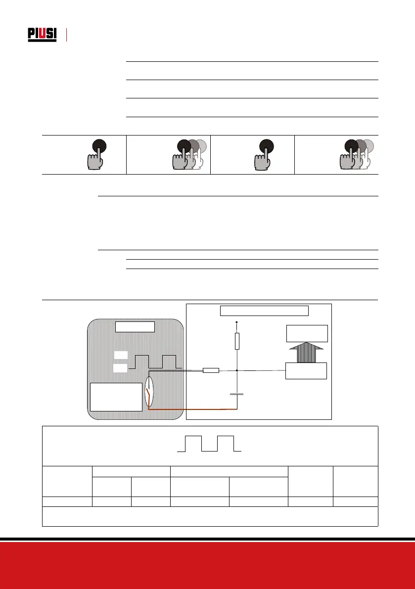
6.1 PULSER INSTALLATION DIAGRAM
R1 Typical 470Kohm
R2 Typical 100 ohm
standard counter of customers
C1 Typical 1nF
Vcc Typical 5 Vdc
Gnd
Reed Switch:
I max = 0,01 mA
for maximum life
expectancy
Pulser Piusi
Microcontroller
CPU
DISPLAY
12345
Gnd
Vcc
Gnd
Vcc
Duty Cicle : THigh/(THigh+TLow) %
R1 Typical 470Kohm
R2 Typical 100 ohm
standard counter of customers
C1 Typical 1nF
Vcc Typical 5 Vdc
Gnd
Reed Switch:
I max = 0,01 mA
for maximum life
expectancy
Pulser Piusi
Microcontroller
CPU
DISPLAY
12345
Gnd
Vcc
Gnd
Vcc
Duty Cicle : THigh/(THigh+TLow) %
MODEL
Flow Rate Field Pulser
Frequency
Signal Max
Square
Wave Duty
Cicle
L/min G/min
Pulse/Liter
(Approximately)
Pulse/Gal
(Approximately)
K24 5-120 1,3 – 31,7 100 379 200 Hz 70-90%
To increase the life expectancy of the flow meters, it is recommended to keep the current value as low
as possible (approx. 0.1 mA)