9/124
9 /20
EN
This manual is the property of PIUSI S.p.A. Any reproduction, even partial, is forbidden.
translated from italian
K24
6.2 METER INSTALLATION
FOREWORD
K24 features a threaded, perpendicular inlet and outlet (1” BSP male and female that can
be combined together). It has been designed to be easily installed in any position: fixed
in-line or mobile on a dispensing nozzle. In order to improve the life of the turbine, it is rec-
ommended to fit a strainer before the meter itself
ATTENTION An F/F coupling, complete with its gasket, is supplied for installations on
male couplings. Always screw the side with gasket on K24.
It is up to the installer to use another gasket on the other side of the cou-
pling.
The gasket used has the following characteristics: flat seal id=24,
od=35.5,thick = 2
Material: NBR 70 SH
For installations on system, position K24 so that the battery housing can
be easily reached.
7 DAILY USE
FOREWORD
The only operations that need to be done for daily use are partial and/or resettable total
register resetting. The user should use only the dispensing system of k24. Occasionally
the meter may need to be configured or calibrated. To do so, please refer to the relevant
chapters.
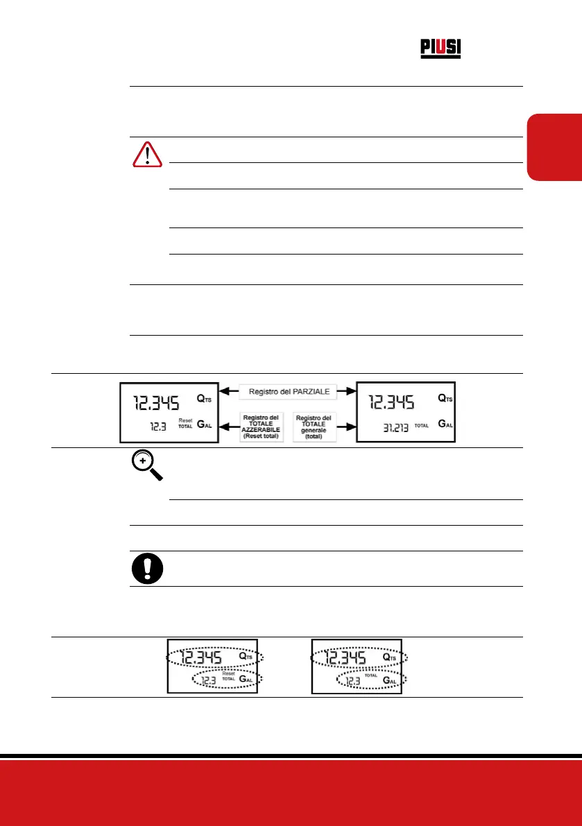
Below are the two typical normal operation displays. One display page shows the partial and reset total
registers. The other shows the partial and general total. Switchover from resettable total to general total
display is automatic and tied to phases and times that are in factory set and cannot be changed.
NOTE 6 digits are available for Totals, plus two icons x 10 / x100. The incre-
ment sequence is the following:
0.0 -> 99999.9 -> 999999 -> 100000 x 10 -> 999999 x 10 ->100000 x
100 -> 999999 x 100
7.1 DISPENSING IN NORMAL MODE
FOREWORD
Normal mode is the standard dispensing. While the count is made, the partial and resetta-
ble total are displayed at the same time (reset total).
WARNING Should one of the keys be accidentally pressed during dispensing, this
will have no effect.
STAND BY
A few seconds after dispensing has ended, on the lower register, the display switches
from resettable total to general total: the word reset above the word total disappears,
and the reset total is replaced by the general total.
This situation is called standby and remains stable until the user operates the k24 again.