10 - ATR902 - User manual
6.1 Numeric indicators (Display)
1
123.4
Usually visualizes mesured temperature, it may visualize also
(programmed temperature)
setpoint value, time elapsed from cycle start, number of
operating step or the percentage value of the command
output. During con guration it visualizes the value of
entering parameter.
2
123 .4
Visualization can be customized with setpoint, time elapsed
from cycle start or number of operating step. During
conguration it visualizes the value of entering parameter.
6.2 Meaning of Status Lights (Led)
3 C1 ON when the heating elements are activaved.
4 A1 ON when alarm 1 is active.
5 TUN ON when controller is executing an auto-tuning cycle.
7 RUN
ON when the device is in START cycle or in “Simple controller”
mode.
Blinking LED indicates the standby of the controller
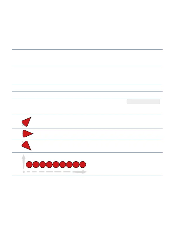
8
ON when the programmer is executing a rising step.
9
ON when the programmer is executing a maintenance step.
10
ON when the programmer is executing a falling step.
11
Cycle progress.
Flashing Led shows the step being
executed; Fixed Led shows the step
already done.