User manual - ATR902 - 9
5 Electrical wirings
This device has been designed and manufactured in conformity to Low Voltage
Directive 2006/95/EC , 2014/35/EU (LVD) and EMC Directive 2004/108/EC, 2014/30/
EU (EMC). For installation in industrial environments please observe following
safety guidelines:
• Separate control line from power wires.
• Avoid proximity of remote control switches, electromagnetic contactors,
powerful engines and use specic lters.
• Avoid proximity of power groups, especially those with phase control.
• It is strongly recommended to install adequate mains lter on power supply of
the machine where the controller is installed, particularly if supplied 230Vac. The
controller is designed and conceived to be incorporated into other machines,
therefore CE marking on the controller does not exempt the manufacturer of
machines from safety and conformity requirements applying to the machine
itself.
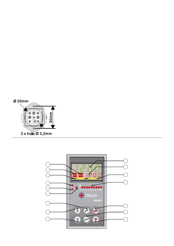
5.1 Wiring diagram
1_ Neutral
2_ Neutral
3_ Thermocouple +
4_ Thermocouple -
5_ Power supply (phase)
6_ Control output (phase)
7_ Aux output (phase)
8_ Not Connected
Optional: multipolar connector (Cod. 0400.70.001).
6 Displays and keys function
1
2
7
11
16
17
13
14
4
3
5
10
8
9
12
15