63
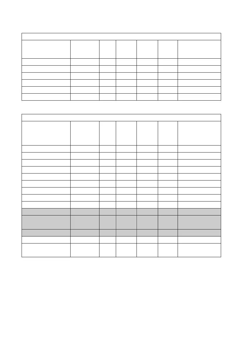
Contact
Notation Min Max Offset R/W Max number of
consecutive bit
read/wrote
External input
“X” 0 9999 0 R 8
External output
“Y” 0 9999 10000 R/W 8
Internal relay
“R” 0 9999 20000 R/W 8
Link relay
“L” 0 9999 30000 R/W 8
Timer
“T” 0 9999 40000 R 8
Counter
“C” 0 9999 50000 R 8
Data Code
Notation Min Max Offset R/W Max number of
consecutive
word
read/wrote
External input
“X” 0 999 0 R 10
External output
“Y” 0 999 1000 R/W 10(R) / 7(W)
Internal relay
“R” 0 999 2000 R/W 10(R) / 7(W)
Link relay
“L” 0 999 3000 R/W 10(R) / 7(W)
Timer
“T” 0 999 4000 R 10
Counter
“C” 0 999 5000 R 10
Index register X
0 0 6000 R/W 1
Index register Y
0 0 6001 R/W 1
Index register D
0 0 6002 R/W 1
Data register
“DT” 0 9999 10000 R/W 10(R) / 7(W)
Link data
register
“LD” 0 9999 20000 R/W 10(R) / 7(W)
File register
“FL” 0 9999 30000 R/W 10(R) / 7(W)
Set value area
0 9999 40000 R/W 10(R) / 7(W)
Elapsed value
area
0 9999 50000 R/W 10(R) / 7(W)
N.B.: On PL260-XX protocol, only elements underlined in grey are enabled
(the other elements have not to be used!). The example below describes
setting for an "EXP" instruction to write on the plc with "1" of 8 consecutive
bit on "external output" Y3 and YA, taking value from VW10.