10 - PL500-PL600-PL700 - User manual
4.1 Mounting sequence of the PLC and of the PLE500
expansion modules
The PLC with the relevant I/O modules requires mounting and connection via
the specific bus lodged in the hollow of the DIN rail. The I/O modules (series
PLE500-xAD) will be automatically numbered at each power-on, assigning the
number 1 to the first I/O module connected to the right of the PLC, the number
2 to the following one and so on, always moving towards the right side. The
position of the various modules shall thus reflect the sequence set in the
LogicLab project in the definition of the PLCEXP network. For the numbering
procedure to work correctly, it is not permitted to remove devices from the
network by releasing them from their own bus and leaving some empty modules
(bus slots) between one module and another. All connection/disconnection
operations must be carried out with power off.
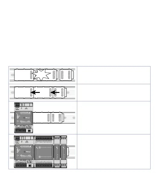
Clik!
Couple all the buses by pushing them
towards the DIN rail, making sure that
the male connection faces left and the
female one faces right.
Couple the buses together by sliding
them along the DIN rail.
Insert the various modules in the slots
of the buses starting from the PLC and
continuing to the right with the I/O
modules.
.4
.5
.6
.7
.3
.2
.1
.0
.4
.5
.6
.7
.3
.2
.1
.0
+0
+1
1 2
3
4
5
6
7 8 9
10
12
QI.0
QI.1
QI.2
QI.3
QI.4
QI.5
QI.6
QI.7
13
14
15 16
17
18 19
20
21 22
23
24
AGND
(0V)
AI0
L+0
AI1
QI.0
QI.1
QI.2
QI.3
QI.4
QI.5
QI.6
QI.7
L+1
AQ.0
AQ.1
AGND
(0V)
10 11 12
1 2 3
10 11 12
1 2 3
Proceed with mounting all the modules
according to the requested order until
the plc is completely formed.