User manual - PL500-PL600-PL700 - 11
.4
.5
.6
.7
.3
.2
.1
.0
.4
.5
.6
.7
.3
.2
.1
.0
+0
+1
1 2
3
4
5
6
7 8 9
10
12
QI.0
QI.1
QI.2
QI.3
QI.4
QI.5
QI.6
QI.7
13
14
15 16
17
18 19
20
21 22
23
24
AGND
(0V)
AI0
L+0
AI1
QI.0
QI.1
QI.2
QI.3
QI.4
QI.5
QI.6
QI.7
L+1
AQ.0
AQ.1
AGND
(0V)
10 11 12
1 2 3
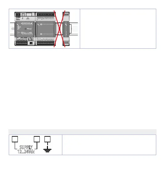
It is not possible to leave free slots
in the bus between one module and
another.
5 Electric connections
This regulator was designed and built in compliance with the Low Voltage
Directives 2006/95/CE, 2014/35/EU (LVD) and the Electromagnetic compatibility
Directives 2004/108/EC and 2014/30/EU (EMC). For installation in industrial
environments it is a good rule to follow the precautions below:
• Distinguish the power supply line from the power lines.
• Avoid proximity with contactor units, electromagnetic contactors, high
power motors and use filters in any event.
• Avoid proximity with power units, particularly if with phase control.
• The use of network filters is recommended on the power supply of the
machine in which the instrument will be installed, particular in case of
230Vac power supply.
The regulator is devised to be assembled with other machines. Therefore,
the EC marking of the regulator does not exempt the manufacturer of the
system from the safety and conformity obligations imposed for the machine
as a whole.
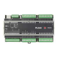
5.a Power supply
SUPPLY
12..24 VDC ± 10%