5
3. Wiring the Power Inputs
The Upper Panel of the Industrial Managed Switch consists of one terminal
block connector within 6 contacts for two redundant power inputs and fault
alarm.Pleasefollowthestepsbelowtoinsertthepowerwire.
1.Insert positive/negative DC power wires into contacts 1 and 2 for Power 1
or5and6forPower2.
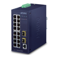
IGS-4215-16T2S
Fault
V1+ V2+
PWR2PWR1
Max. fault loading: 24V, 1A
DC Input: 12-48V , 1.5A max.
AC
Input: 24V , 1A max.
1 2 3 4 5 6
Figure 3-1: IGS-4215-16T2S Inlet Power Socket
IGS-4215-16T2S-U
Alarm
V1+ V2+
PWR2PWR1
DC Input: 9-48V , 1.5A max.
AC
Input: 24V , 1A max.
Max. Fault Alarm Loading: 24V, 1A
1 2 3 4 5 6
Figure 3-2: IGS-4215-16T2S-U Inlet Power Socket
 Loading...