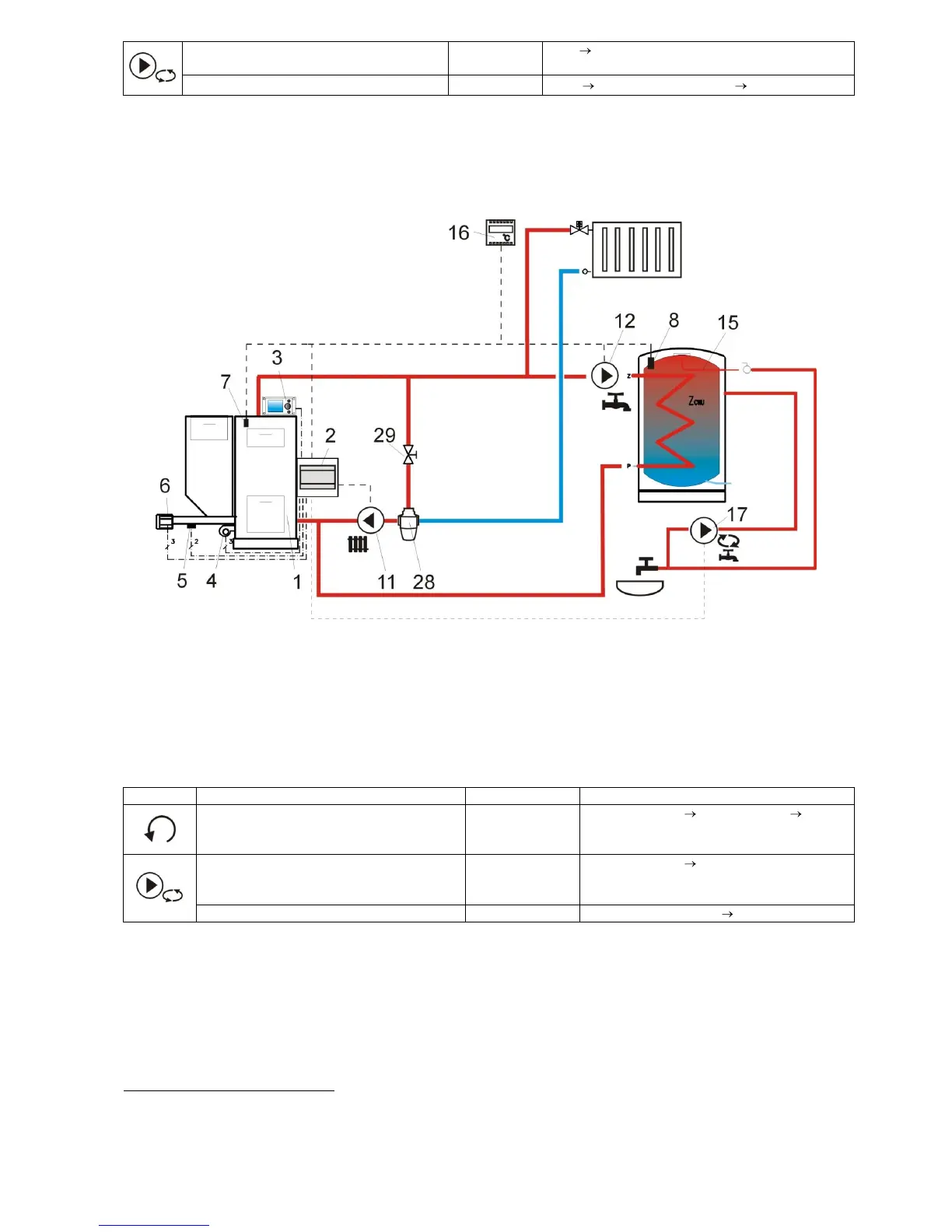
8.2 Diagram 2
Fig. 15 Diagram with 3-way thermostatic valve to secure return water temperature
5
, where: 1 –
boiler, 2 – ecoMAXX regulator – module A, 3 – ecoMAXX regulator – control panel, 4 – fan, 5 – feeder
temperature sensor, 6 - gear-motor, 7 – boiler temperature sensor, 8 – HUW temperature sensor, 9 - mixer
temperature sensor, 10 – temperature (weather) sensor, 11 – CH circuit pump, 12 – HUW circuit pump, 13
– mixer circuit pump, 15 – HUW container, 16 – room thermostat or ecoSTER200, 17 – HUW circulating
pump, 27 –return temperature sensor (does not affect combustion process control), 28 – thermostatic 3-
way valve, 29 – throttle (mushroom) valve.
RECOMMENDED SETTINGS:
Service Settings Boiler Settings Return
Protection 4D (if mixer sensor in not
provided - this option is not available)
5
The presented hydraulic diagram does not replace central heating engineering design and may be used for
information purposes only.

 Loading...