8.4 Schemat 4
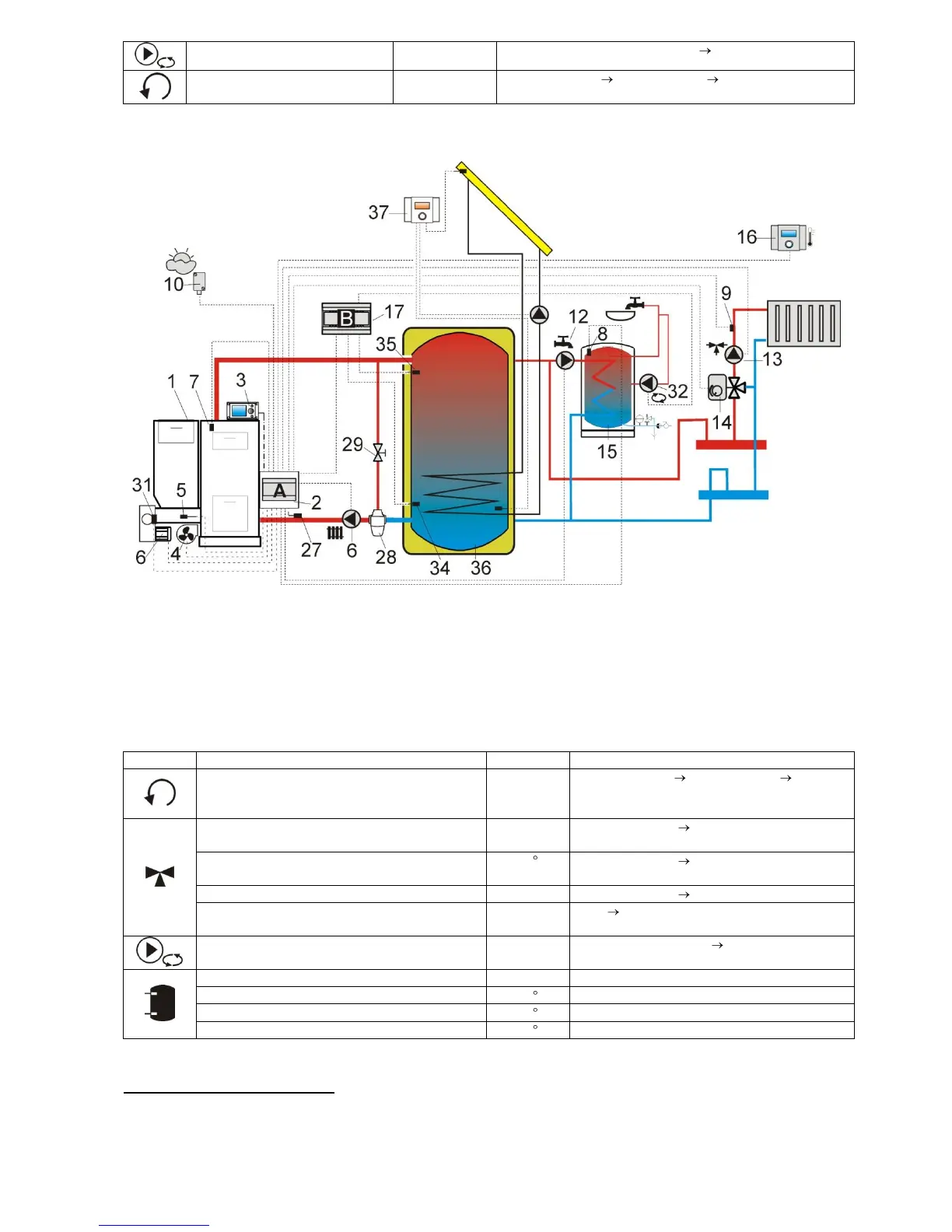
Fig. 17 Diagram with heat buffer and additional module B
9
, where: 1 – boiler, 2 – ecoMAXX regulator
– module A, 3 – ecoMAXX regulator – control panel, 4 – fan, 5 – feeder temperature sensor, 6 - gear-motor,
7 – boiler temperature sensor, 8 – HUW temperature sensor, 9 - mixer 1 temperature sensor, 10 –
temperature (weather) sensor, 12 – HUW circuit pump, 13 – mixer 1 circuit pump, 14 – mixer 1 servo, 15 –
HUW container, 16 – ecoSTER200 room control panel with room thermostat function, 17 – extension module
B, 27 – return temperature sensor, 28 – thermostatic 3-way valve (to protect boiler return), 29 - throttle
mushroom valve, 32 – HUW circulating pump, 34 – lower buffer sensor, 35 – upper buffer sensor, 36 – heat
buffer, 37 – additional solar ecoSOL regulator.
Service Settings Boiler Settings Return
Protection 4D (if mixer sensor in not provided
- this option is not available)

 Loading...