27
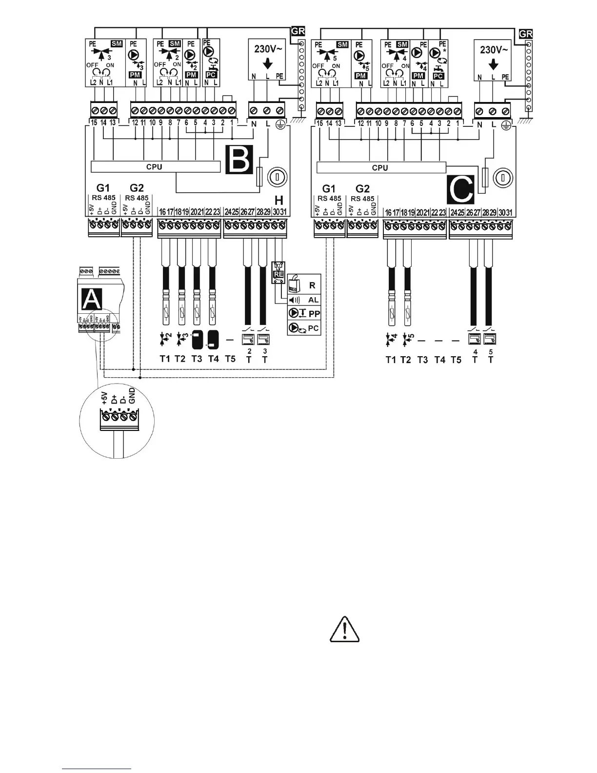
Fig. 26 Wiring diagram - modules B and C: T1 – mixer 2 or 4 temperature sensor CT4, T2 – mixer 3 or 5
temperature sensor CT4, T3 – upper temperature sensor of the buffer, T4 – lower temperature sensor of the buffer
CT4, T5 – reserve, RE – relay (5÷6V, max 80mA) to connect reserve boiler R, alarm AL, boiler shunt pump PP, or
HUW circulating pump PC , T – room thermostat, R – reserve boiler, AL – alarm annunciator, PP – boiler shunt
pump to protect boiler return , PC – HUW circulating time, B – extension module (two heating circuits, heat buffer,
HUW circulating time), C (MX.03) – extension module (two additional heating circuits), power supply cable, 230V
AC , PM – mixer pump, SM – mixer servo, PC – HUW circulating time, * - HUW circulating pump available in
module C from software version mod_A_v.01.31.21, GR – ground strip.
11.7 Temperature sensors connection
Wires of the sensors can be extended by
wires with diameter not smaller than
0,5mm
2
. Total lenght of wires in each sensor
should not exceed 15m.
Boiler temperature sensor should be installed
in thermostatic pipe installed in boiler.
Temperature sensor of hot water silo should
be installed in thermostatic pipe welded into
the silo. Mixer temperature sensor should be
installed in sleeve located in stream of
running water in pipe, but also it can be
installed on the pipe, on condition that it is
thermo isolated from the pipe
 Loading...