31
limit switches), note: contacts 22, 21, 24 must
have galvanic separation from contacts 12,11,14.
11.13 Connection of alarm signalling
The regulator may announce alarm condition
by activating external device (e.g. bell or
GSM device to send SMS). Alarm signalling
and reserve boiler control use the same
terminals, therefore, setting of output H at
alarm signalling deactivates the function of
reserve boiler control. Connect alarm
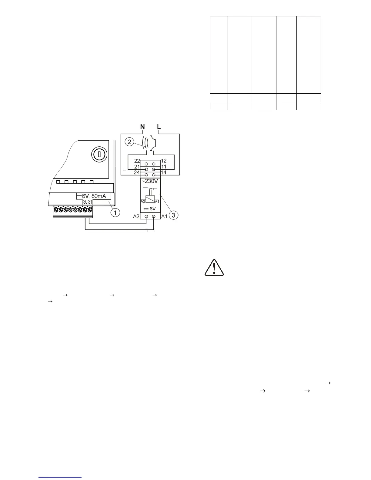
annunciator as shown in Fig. 31 through U3
module.
Fig. 31 Connection of external alarm annunciator 1-
ecoMAXX800 regulator - module A, 2 –external alarm
annunciator, 3 –relay RM 84-2012-35-1006 RELPOL and
base GZT80 RELPOL,
For proper operation, set proper value of the
parameter: Active alarm signal code in:
MENU Service Settings Boiler Settings Alarms
Active alarm signal code
When "31" has been set - in case of any
alarm occurred, voltage is applied at contact
30-31. Setting this parameter at "0" causes
the regulator does not apply voltage upon
occurrence of any alarm. Contact 30-31 may
be so set up that the voltage will be applied
at it upon occurrence of one or few alarms.
The values of this parameter to be set for
respective alarms are given in the table
below:
CH boiler temperature
sensor damage
Feeder temperature
sensor damage
Example: when this parameter is set at ,”8”,
voltage will be applied at the contact only
upon occurrence of AL4 alarm. In case of
,”1” setting, only alarm ,”1” will be
announced. In case the contact should signal
few alarms (e.g. AL2 and AL4 alarms) - sum-
up the values indicated in the table for
individual alarms (i.e. 2 + 8 = 10) and set so
calculated sum. For signalling alarms: AL1,
AL2 and AL3 - set ,”7” because the sum of 1
+ 2 + 4 = 7.
11.14 Connection of mixer servo
When connecting electric servo of
the mixer take due care to
prevent boiler overheating, which
may occur when the flow of boiler
water is limited. You are advised
to get familiar with the position of
the valve corresponding to its
maximum opening before
commencement of work so that
you may ensure heat collection
from the boiler at any time it is
required.
The regulator works only with mixing valve
servos equipped with limit switches. Use of
other servos is not allowed. The servos of full
turn time from 80 to 255 s may be used.
Description of mixer servo connection:
- connect mixer temperature sensor,
- switch on the regulator and select proper
mixer support in service menu: MENU
Service Settings PASSWORD Mixer
Settings - e.g. "CH ON ”.
- enter proper Valve Opening Time (Valve
Opening Time ) in Service Settings (this time
should be indicated on servo rating plate e.g.
120s),
- disconnect power supply of the regulator,

 Loading...