30
Set the temperatures of reserve boiler switch
on/off:
MENU SERVICE SETTINGS BOILER
SETTINGS Reserve Boiler Reserve
boiler deactivation temperature . Control of
reserve boiler is off upon setting this
parameter at ,,0”. Now, set-up Output H on
reserve boiler:
MENU Service Settings OUTPUT H =
reserve boiler
Once the retort boiler has been fired up, and
its temperature has exceeded the preset
value (e.g. 25 C), ecoMAXX 800 regulator
switches off the reserve boiler and applies
voltage 6V DC at Output H, which causes
release of coil of U3 module relay and
opening its contacts. Once the boiler
temperature has dropped below the value set
in the parameter of Reserve boiler
deactivation temperature , the regulator
stops to supply voltage to Output H, and the
reserve boiler switches on.
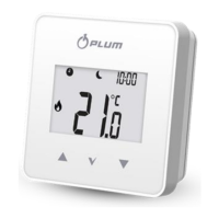
Fig. 28
8
. . Hydraulic diagram with reserve boiler;
connection of open and close circuits 1 –ecoMAXX
regulator , 2 – reserve boiler, 3 – U3 module (2
pcs), 4 – switching valve (with limit switches), 5 –
heat exchanger (recommended settings: HUW
mode = no priority, heat exchanger = ON (Menu
Pump Service Settings .
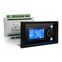
Fig. 29
15
. Hydraulic diagram with reserve boiler and 4-
way valve in close circuit 1 – ecoMAXX regulator, 2 –
reserve boiler, 3 – U3 module, 2 pcs., 4 – switching
valve servo (with limit switches) - to ensure free
gravitational flow of water in boiler circuit, active cross-
section of switching valve (4) has to be larger than or
equal to cross-section of boiler circuit pipes. Use pipes of
large cross section for gravitational boiler circuit.
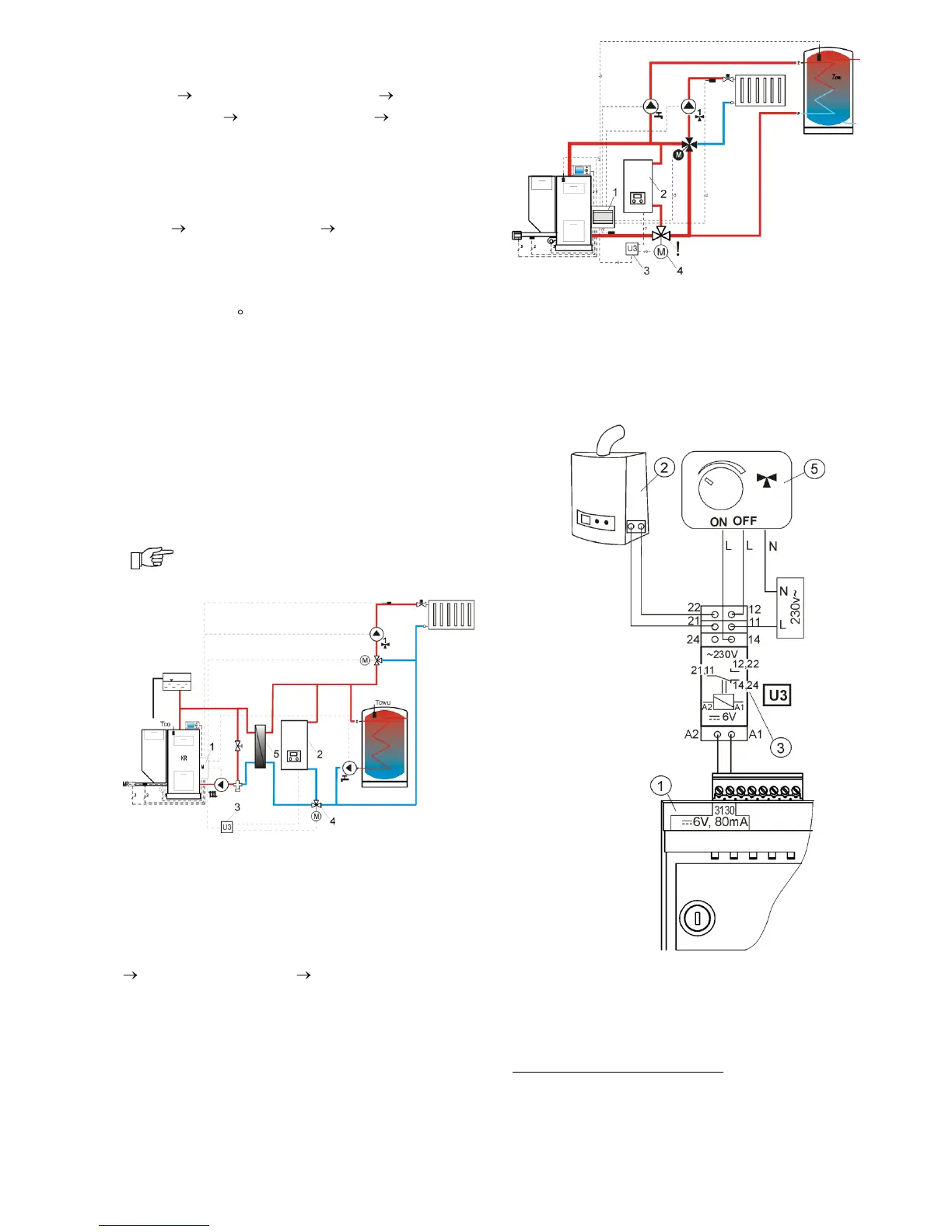
Fig. 30. Electric diagram for switching valve of the
reserve boiler, where: 1 – regulator
ecoMAX800P1-L module B, 2 – reserve boiler, 3 –
U3 module, 5 – servo of switching valve (with
15
The presented hydraulic diagrams do not
replace central heating engineering design and
may be used for information purposes only.
 Loading...