26
Condition of PM pump operation is the setting: Service Settings Mixer 1 Settings Mixer support =
pump only (in case mixer sensor T4 is not installed, this option is not available)
Condition of PC pump operation is the setting: Service Settings Mixer 1 Settings Mixer support =pump
only or = OFF (in case mixer sensor T4 is not installed, this option is not available)
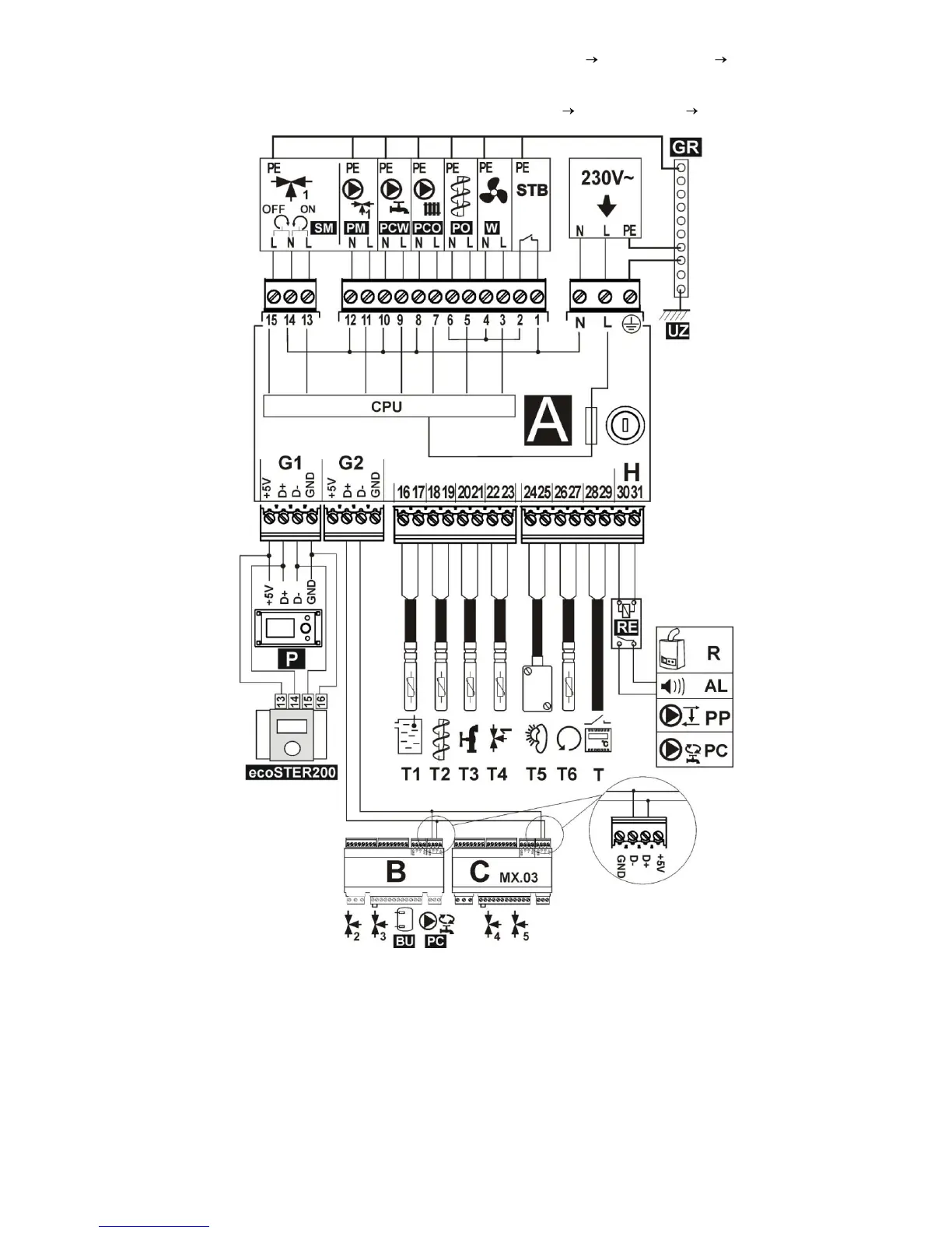
Fig. 25 Wiring diagram – with electric servo of valve T1 – boiler temperature sensor CT4, T2 – fuel feeder
temperature sensor CT4, T3 – HUW temperature sensor, T4 – mixer 1 temperature sensor CT4, T5 – out-door
temperature sensor - type CT4-P, T6 – boiler return water temperature sensor, RE – relay (5÷6V, max 80mA) to
connect reserve boiler R, alarm AL, boiler shunt pump PP, or HUW circulating pump PC , T – room thermostat, R –
reserve boiler, AL – alarm annunciator, PP – boiler shunt pump to protect boiler return , PC – HUW circulating time,
P – boiler control panel, B – extension module (two heating circuits, heat buffer, HUW circulating time), C MX.03 –
extension module (two additional heating circuits), power supply cable, 230V AC , STB – safety temperature limiter
(disconnects feeder and blow-in), W – fan, PO - fuel feeder motor, PCO – boiler pump, PCW – HUW pump, PM –
no.1 mixer pump, SM – mixer servo, GR – ground strip, UZ – earthing of metal regulator housing.
 Loading...