25
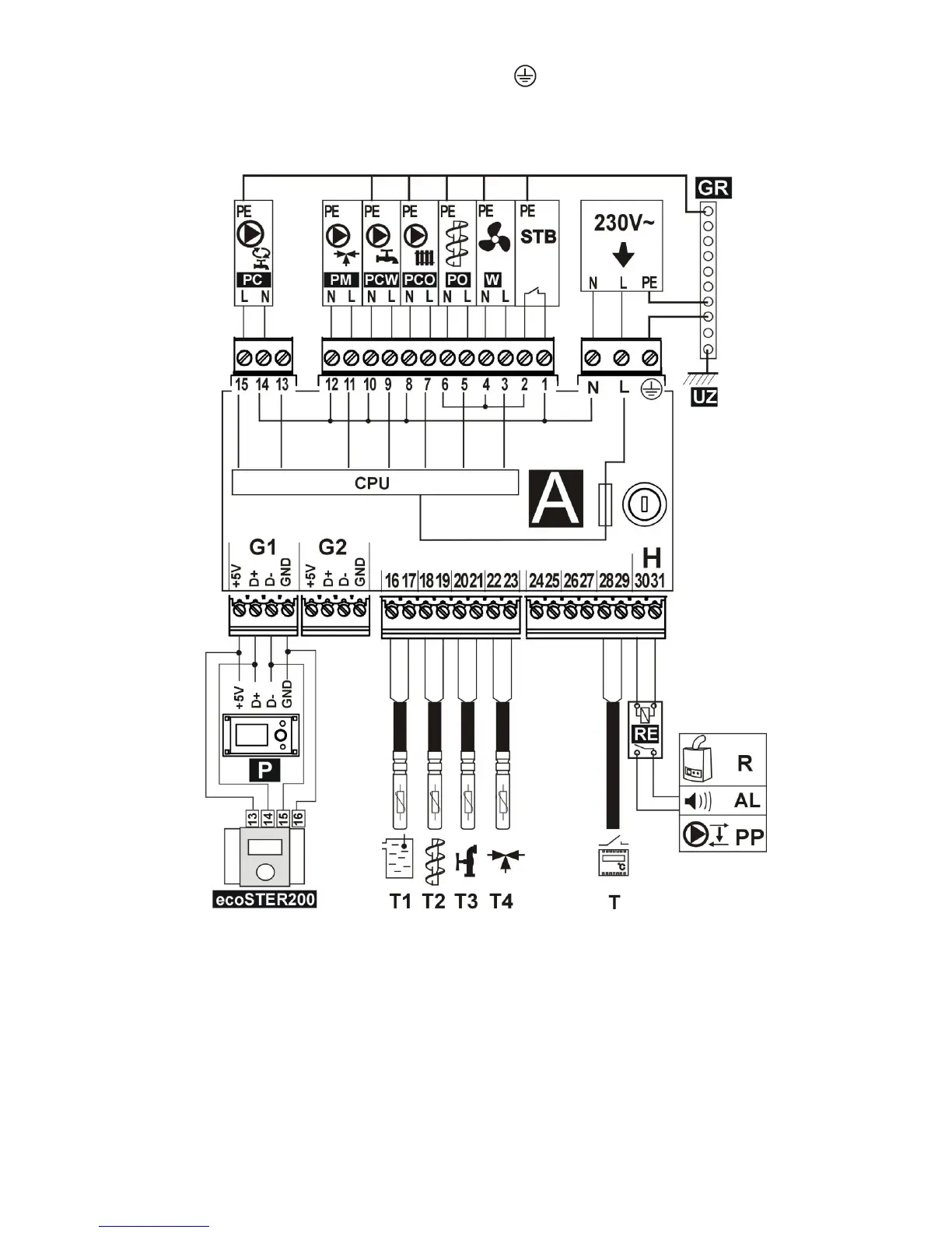
The protective conductor of the feeder cable
should be connected to a neutral strip
contacted with the metal casing of the
regulator. The fitting should be connected to
the regulator terminal marked with symbol
and with grounding terminals of the
devices connected to the regulator. (Fig.
25).
Fig. 24 Wiring diagram - four pumps T1 – boiler temperature sensor CT4, T2 – fuel feeder temperature sensor
CT4, T3 – HUW temperature sensor, T4 – underfloor heating circuit sensor (thermostatic valve without electric
servo), T – room thermostat, R – reserve boiler, AL – alarm annunciator, PP – boiler shunt pump to protect boiler
return , P – boiler control panel, power supply cable, 230V AC , STB – safety temperature limiter (disconnects
feeder and blow-in), W – fan, PO-fuel feeder motor, PCO – boiler pump, PCW – HUW pump, PM – thermostatic
mixer circuit pump (without electric servo) to underfloor heating, GR – ground strip, UZ – earthing of metal
regulator housing, PC – HUW circulating pump (instead of mixer servo), RE – relay (5÷6V, max 80mA),
 Loading...