CR Family Hardware
Installation Guide
CR Family Hardware Installation Guide Page 26 of 30
Copyright © 2016 by Pointer Telocation, Ltd.
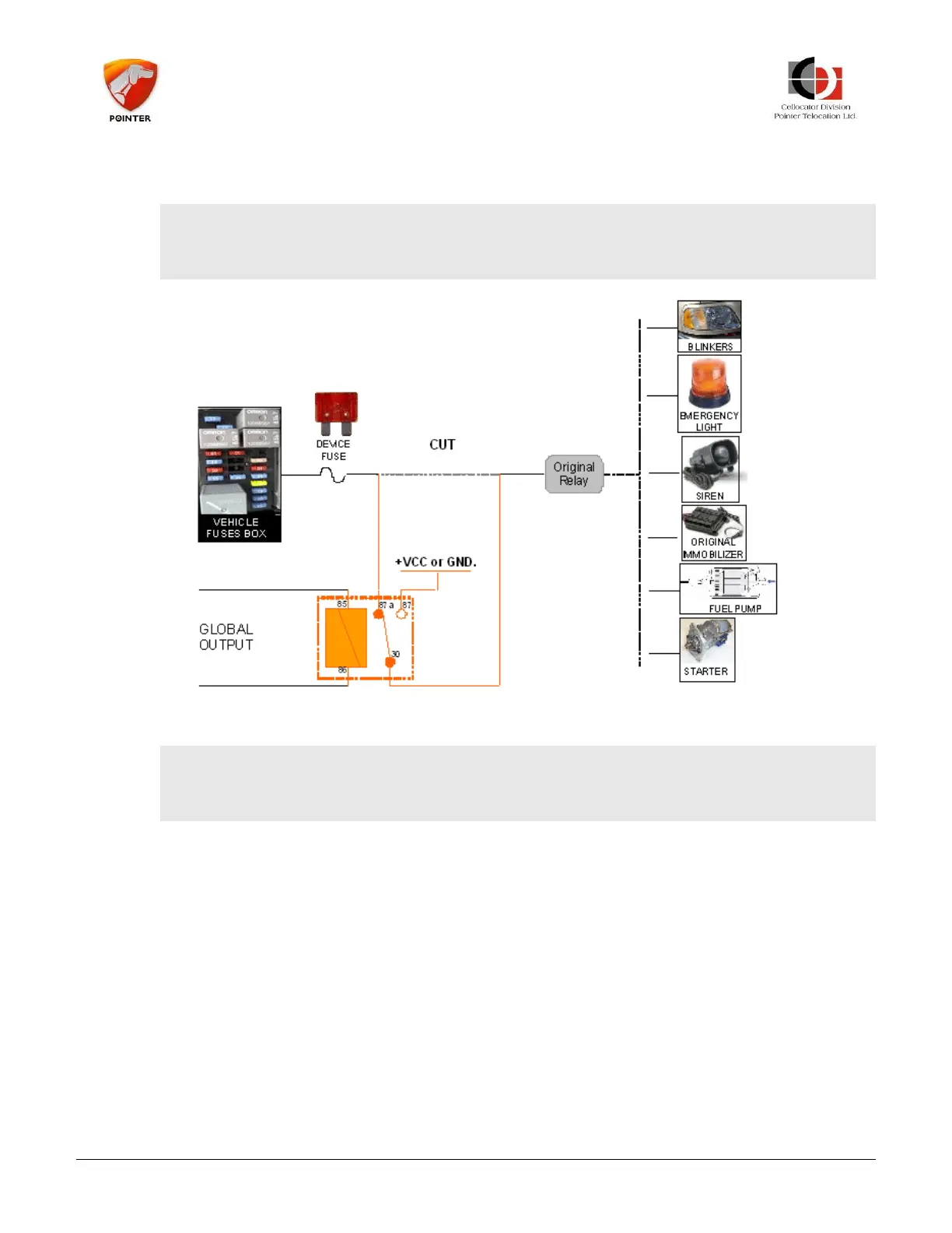
It can be activated/deactivated by an OTA command from the control center. The
following illustration provides the Global Output installation.
---------------------------------------------------------------------------------
NOTE: The original wire must be cut and the relay connected between the original relay
and the vehicle power.
---------------------------------------------------------------------------------
Figure 17: Global Output Installation Diagram
---------------------------------------------------------------------------------
NOTE: Configuration can be programmed to support Immobilizer functionality on each
one of the two outputs.
---------------------------------------------------------------------------------
5.2 Harness Inputs Installation Specifications
5.2.1 Global Purpose Input (Shock)
The harness Global Purpose Input (Shock) yellow wire is connected to the CR unit pin no.
9 and used for general purpose input.
5.2.2 Door Input
The harness Global Purpose Input (Door) pink wire is connected to the CR unit pin no. 5
and used for general purpose input.
5.2.3 Ignition Input
The harness Ignition Input Violet wire is connected to the CR unit pin no. 4 and should be
connected to the ignition switch (in the ON position).