7.5
ELECTRICAL
7
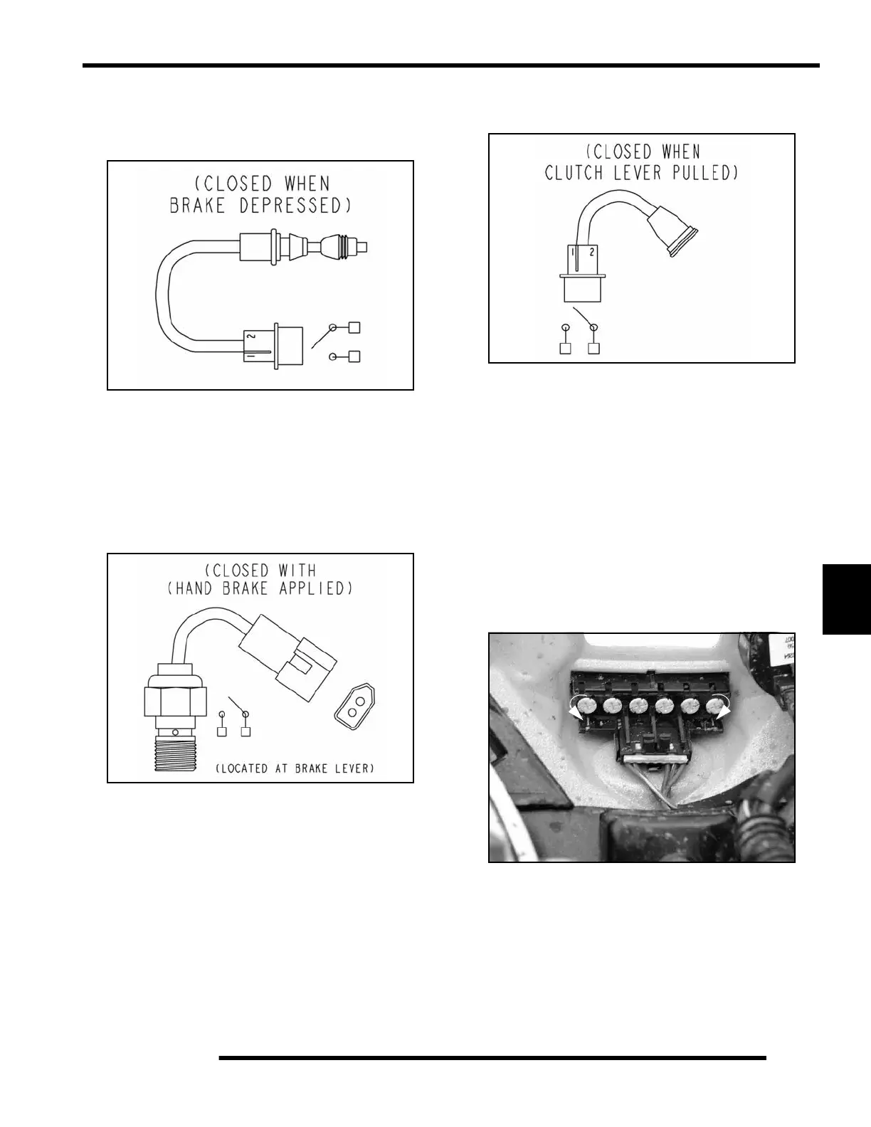
Brake Light Switch Tests
Foot Brake Switch
1. Disconnect wire harness from switch.
2. Connect an ohmmeter across switch contacts. The circuit
should have an open line or infinity reading.
3. Apply foot brake and check for continuity between switch
contacts. Replace switch if there is no continuity or greater
than .5 ohms resistance when the brake is applied with
slight pressure.
Hand Brake Switch
1. Disconnect wire harness from switch.
2. Connect an ohmmeter across switch contacts. The circuit
should have an open line or infinity reading.
3. Apply front brake lever and check for continuity between
switch contacts. Replace switch if there is no continuity or
greater than .5 ohms resistance when the brake is applied
with slight pressure.
Clutch Switch Test
1. Disconnect wire harness from switch.
2. Connect an ohmmeter across switch contacts. The circuit
should have an open line or infinity reading.
3. Apply the clutch lever and check for continuity between
switch contacts. Replace switch if there is no continuity or
greater than .5 ohms resistance when the lever is applied
with slight pressure.
Indicator Lamp Replacement
1. Gain access to the lamps by disconnecting the front cab
harness and removing the fasteners that attach the front cab
to the ATV.
2. Disconnect wire harness connector at indicator panel.
Remove indicator lamp from the panel by turning the
holder 1/4 turn with a screw driver (A).
3. Push a new lamp into holder assembly and insert into the
indicator panel. Turn holder 1/4 turn to lock in place (B).
Reconnect wiring and reattach the cab assembly.
A
B
 Loading...