EasyManua.ls Logo

Polaris SPORTSMAN 600 2003 Service Manual

Polaris SPORTSMAN 600 2003
262 pages
To Next Page IconTo Next Page
Page #1 background imageLoading...
Page #1 background image
PN 9918066
Printed in USA
2002-2003 SPORTSMAN 600/700 SERVICE MANUAL PN 9918066
2003 SPORTSMAN 600
2002-2003 SPORTSMAN 700
SERVICE MANUAL
PN 9918066
223336_coverB 9/17/02 10:22 PM Page 1

Table of Contents

Question and Answer IconNeed help?

Do you have a question about the Polaris SPORTSMAN 600 2003 and is the answer not in the manual?

Polaris SPORTSMAN 600 2003 Specifications

General IconGeneral
BrandPolaris
ModelSPORTSMAN 600 2003
CategoryOffroad Vehicle
LanguageEnglish

Summary

Understanding Safety Labels and Instructions

Trademarks

Lists recognized product trademarks used in the manual.

2003 SPORTSMAN 600/700 SERVICE MANUAL

Foreword

Provides introductory information and guidance for using the service manual.

Chapter 1 General Information

Model Identification

Details how to identify the machine's model number for service and warranty.

Standard Torque Specifications

Lists general torque specifications for fasteners used in various vehicle components.

Chapter 2 Maintenance

Periodic Maintenance Chart

Outlines recommended inspection, adjustment, and lubrication intervals for components.

Pre-Ride / Daily Inspection

Lists essential checks to perform before operating the vehicle for safety and performance.

Recommended Lubricants

Special Tools

Gearcase Lubrication

Carburetor Adjustments

Fuel System

Battery Maintenance

Spark Plug

Cooling System Hoses

Coolant Level Inspection

Air Filter/Pre-Filter Service

Engine Oil Level

Oil and Filter Change

Tie Rod End / Steering Inspection

Wheel Alignment Method 1: Straightedge or String

Brake System Inspection

Auxiliary Brake Adjustment (Hydraulic)

Suspension: Spring Preload Adjustment

Wheels

Tire Pressure

Tire Inspection

Chapter 3 Engine

Engine Exploded Views

Detailed exploded diagrams of various engine assemblies for identification and service.

Torque Specifications

Lists torque specifications for engine fasteners, essential for proper assembly.

Engine

Engine Exploded View (Crankcase)

Exploded view of the engine crankcase, detailing its components and assembly.

Engine

Engine Exploded View (Crankshaft and Pistons, Valve Train)

Exploded views of the crankshaft, pistons, and valve train components for service.

Special Tools

Engine Fastener Torque Patterns

600 Engine Service Data

Cooling System Specifications

Engine Remove & Install

Engine Break In Period

Cylinder Hone Selection and Honing Procedure

Oil Pressure Test

Rocker Arm Inspection

Cylinder Head Removal

Cylinder Head Warpage

Valve Inspection

Valve Seat Reconditioning

Cylinder Head Reassembly

Valve Sealing Test

Engine Head Reassembly

Cylinder Removal

Piston Removal

Cylinder Inspection

Piston-to-Cylinder Clearance

Piston/Rod Inspection

Starter Drive/Bendix Removal/Inspection

Flywheel/Stator Removal/Inspection

Flywheel/Stator Installation

Engine Lower Disassembly/Inspection

Cam Gear Removal

Water/Oil Pump Removal/Disassembly

Camshaft Inspection

Engine Lower Reassembly

Gear/Stator Housing Seal Replacement

Starter Reassembly

Starter Solenoid Bench Test

Troubleshooting

Cooling System Troubleshooting

Bleeding Procedure for 4-Stroke Cooling Systems

Chapter 4 Fuel System/Carburetion

Exploded View, Mikuni BST 40 Carburetor

Detailed exploded view of the Mikuni BST 40 carburetor, identifying all components.

Jetting Guidelines

Explains how altitude and temperature affect air density and jetting requirements for optimal combustion.

CV Carburetor System Function

Carburetor Operation Cont’d

Float System

Carburetor Cleaning

Carburetor Inspection

Float Height Adjustment

Fuel Pump Inspection/Assembly

Troubleshooting

Chapter 5 Body / Steering / Suspension

Body Assembly, Exploded View

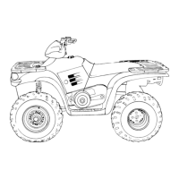
Exploded view of the ATV's body parts, including front and rear cab assemblies.

Steering/A-Arm Exploded View

Exploded view of the steering and A-arm systems, illustrating component placement and torque values.

Body Assembly Exploded View

Steering/A-Arm Exploded View

Rear Suspension Exploded View

Front Strut Assembly Exploded View

Special Tools

Torque Specifications

A-Arm Replacement

Steering Post Assembly

Front Strut Cartridge Replacement

Ball Joint Replacement

Decal Replacement

Chapter 6 Clutch

Drive Clutch Exploded View

Exploded view of the drive clutch assembly, identifying all components.

PVT Maintenance/Inspection/Drying

Guidelines for maintaining and inspecting the PVT system for optimal performance and longevity.

Drive Clutch Exploded View

Engine Braking System (EBS) Exploded View

PVT Operation Overview

PVT Maintenance/Inspection

PVT Overheating/Dianosis

PVT Disassembly

PVT Assembly/Inspection

Drive Clutch Spring Specifications

Shift Weights

Drive Clutch Disassembly

Spider Removal

Drive Clutch Reassembly

Drive Belt Removal/Inspection

Drive Belt Installation

Clutch Alignment

Clutch Offset

Drive Clutch Inspection

EBS Driven Clutch Disassembly/Inspection

Roller Pin Disassembly

EBS Drive Bushing Service

EBS Drive Clutch Cover Bushing Removal

EBS Driven Bushing Service

Troubleshooting

Chapter 7 Final Drive

AWD Axle/Propshaft Exploded Views

Exploded views of AWD axle and propshaft components, detailing their arrangement.

Front Drive Axle Removal

Step-by-step guide for removing the front drive axle from the ATV.

AWD Front Drive Axle Exploded View

Special Tools

Wheel and Hub Torque Table

Front Hub Inspection

Driveshaft and CV Joint Handling Tips

Front Drive Shaft CV Joint Boot Replacement

Front Hub Disassembly

Front Prop Shaft Removal

U-Joint Disassembly

U-Joint Reassembly

Front Gearcase Removal

Front Gearcase Operation -- Centralized Hilliard

Front Gearcase Disassembly/Inspection

Front Gearcase Disassembly/Inspection (Cont.)

Front Gearcase Reassembly/Inspection

Front Gearcase Diagnosis

Front Housing Installation

Front Gearcase Exploded View

Rear Hub Removal

Rear Hub Installation

Rear Hub Disassembly

Rear Hub Assembly

Rear Drive Shaft Removal

Driveshaft and CV Joint Handling Tips

Rear Drive Shaft Installation

Rear Drive Shaft Service

Rear Gearcase Removal

Rear Gearcase Installation

Rear Gearcase Disassembly

Rear Gearcase Reassembly

Rear Gearcase Reassembly (Cont.)

Rear Gearcase Exploded View

Chapter 8 Transmission Service

Transmission, Exploded View

Exploded view of the transmission assembly, identifying all components.

Transmission Removal

Step-by-step procedure for removing the transmission from the ATV frame.

Transmission Exploded View

Torque Specifications

Gear Selector Removal

Transmission Removal Cont’d

Transmission Installation

Transmission Disassembly Cont’d

Transmission Disassembly Cont’d

Transmission Disassembly Cont’d

Transmission Disassembly Cont’d

Transmission Disassembly Cont’d

Transmission Reassembly

Transmission Reassembly Cont’d

Transmission Reassembly Cont’d

Transmission Reassembly Cont’d

Chapter 9 Brakes

Special Tools/Specifications/Torques

Lists special tools, specifications, and torque values for brake system service.

Hydraulic Brake System Overview

Explains the hydraulic brake system's operation, including master cylinder, caliper, and fluid dynamics.

Special Tools

Specifications

Brake System Service Notes

Brake Noise Troubleshooting

Hydraulic Brake System Operation Overview

Hydraulic Caliper Bleeding

Brake Bleeding - Fluid Change

Master Cylinder Removal

Master Cylinder Installation

Front Pad Removal

Front Pad Assembly

Front Disc Inspection

Brake Burnishing Procedure

Front Brake Disc Removal / Replacement

Front Caliper Removal

Front Caliper Disassembly

Front Caliper Inspection

Front Caliper Reassembly

Front Caliper Installation

Front Brake Caliper Exploded View

Rear Brake Pad Removal

Rear Brake Pad Installation

Rear Caliper Removal/Inspection

Rear Caliper Assembly

Rear Brake Disc Inspection

Troubleshooting

Rear Brake Caliper Exploded View

Rear Auxiliary Master Cylinder

Chapter 10 Electrical

330 Watt Alternator Exploded View

Exploded view of the 330-watt alternator, showing its components and location.

Timing Check Procedure

Step-by-step guide for checking ignition timing using a timing light and identifying timing marks.

Instrument Cluster Troubleshooting

Guide for diagnosing and resolving issues with the instrument cluster, including speed, RPM, and warning lights.

Components of 600/700 300 Watt Alternator

Flywheel Identification

Timing Check Procedure

Trigger Coil Gap

Gear Position Indicator Switch Test

Instrument Cluster Troubleshooting

Program Service Interval Cont’d

Speedometer Removal

Speedometer Installation

Speedometer Troubleshooting

Speedometer Troubleshooting

Speedometer Troubleshooting

Coolant Temperature Sensor Test (Hot Light)

Fan Control Circuit Operation / Testing

Electronic Throttle Control (ETC) Switch

Ignition System Testing Flow Chart

Ignition System Troubleshooting

CDI Output Test Using Peak Reading Adaptor

Charging System “Break Even” Test

Alternator Output Test (AC Amp)

Charging System Testing Flow Chart

Initial Battery Activation

Battery Inspection/Removal

Battery Testing

Load Test

Off Season Storage

High Beam Headlight Adjustment

High Beam Headlight Lamp Replacement

Lower Headlamp Removal/Installation

Taillight/Brakelight Lamp Replacement

Starter Motor Disassembly

Brush Inspection/Replacement

Armature Testing

Starter Reassembly

Starter Solenoid Bench Test

Starter Drive

Starter Assembly

Starter System Testing Flow Chart

Wiring Diagram 2002 Sportsman 700

Wiring Diagram 2003 Sportsman 600/700

Related product manuals