12
Repair Manual Addendum Disassembly/Reassembly
11. Using fingers, gently disconnect the following flex circuits (Figure 2-9) from the strobe
PC board connectors:
• S12
•J1
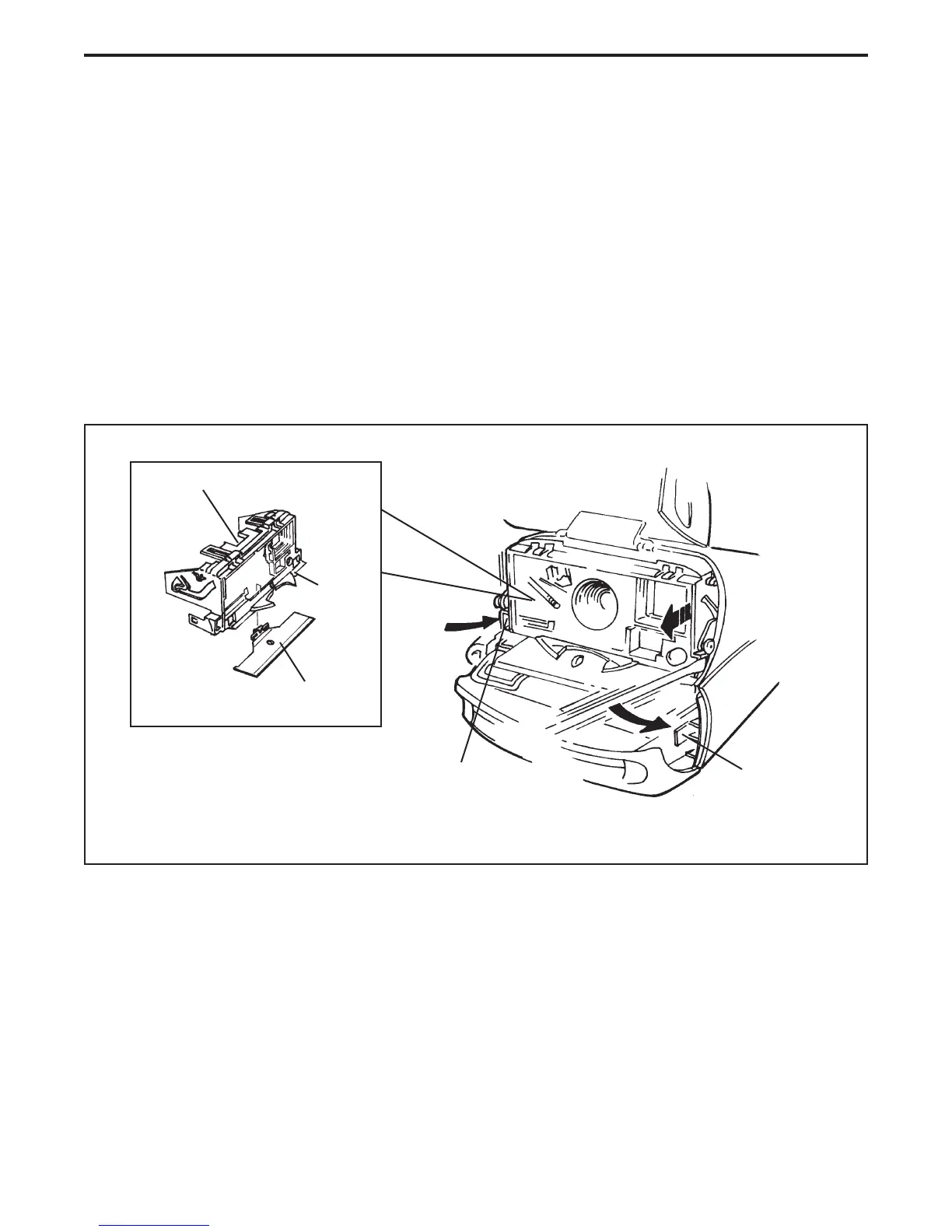
12. Using a small flat screwdriver, remove the upper apron assembly from the body as
follows:
• Insert the small flat screwdriver between plastic body tab and the upper apron locking
tab (Figure 2-10) at the non-gear side of the upper apron assembly.
• Gently twist the flat screwdriver to release the upper apron locking tab being careful not
to scratch or damage the upper apron or body assembly.
Figure 2-10. Removing upper apron assembly
• Gently pull out the non-gear side of the upper apron assembly to release it.
• Repeat this procedure to release gear side of the upper apron assembly.
• Lift off the upper apron assembly.
Note: Removing the upper apron assembly releases the lower housing/strobe
assembly from the body hinge - it just falls out (Figure 2-11).
Upper Apron Assembly
Plastic Body Tab
(Non-Gear Side)
Trim Actuator/Button
Locking Tab
Location
(Gear Side)
Trim Actuator
Slide Post
 Loading...