61
R
S
4
8
5
A
+
B
-
H
o
m
e
K
i
t
S/A2
E/M T Z1 Z2 Z3 Z4
Z8 Z7 Z6 Z5 B2 B1
N L
RS485
A+ B-
S1
S2
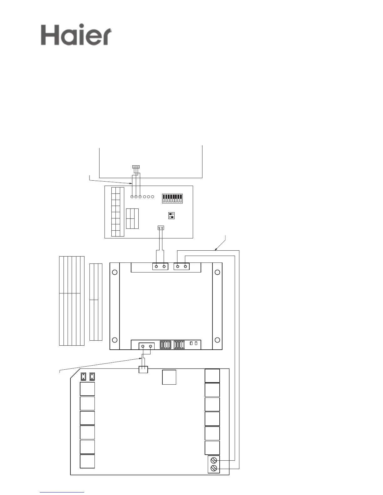
S/A1-2: Supply Air Sensors
E/M: Extension Module
T: Touchscreen
Z1...Z8: Zone Dampers
L and N: 24V AC Power Supply
B1 and B2: Bypass Dampers
HomeKit: HomeKit Module
RS485: AC Gateway
AC Gateway
CN24
AirTouch 4
S/A1
V1 V2
A B
YCJ-A002 Adaptor
12
COM1 G
CN1
B
A
SW1
BM1
ON
ON
1 2
657211 (RS485 Cable) from Polyaire
(Provided with the gateway)
Gateway ID Setting
S2
ID
0001 Haier
Three wire cable with plugs
(Provided with YCJ-A002)
(From Haier)
AC Indoor PCB
Gateway Address Setting
S1
Gateway Address
1000 1
0100 2
1100 3
0010 4
657222
Note: 0-Off, 1-On
Two stripped wires
(field prepared)
BM1
1
2
0 1
SW1
1 2 3 4 5 6 7 8
0 0 0 0 0 0 0 0
Note: 0-Off, 1-On
Wiring Diagrams contd.
1. Wire AirTouch, gateway, YCJ-A002 (supplied by Haier) and AC indoor as per
diagram. Make sure all wires are connected properly
2. Set the dipswitch settings on the YCJ-A002 and the gateway as shown on the
drawing as required
3. In default, AC will use its own return air sensor as control sensor. Installers can
set the AC control thermistor to an AirTouch 4 sensor by going to AC detail
setting in Installer’s Settings of AirTouch 4.