7
Eight motorized dampers can be connected to the main control module.
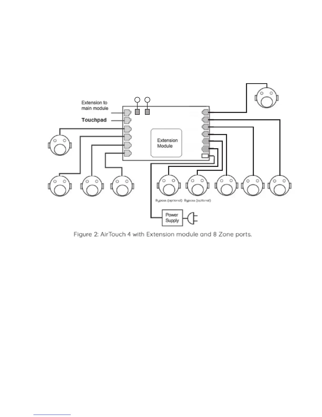
Nine dampers and above (up to 16) will need the extension module.
The wiring of the AirTouch 4 system is straightforward. A cable with central latched
plugs connects a motorized damper to the relevant output port clearly marked on
the main or extension module. Figure below shows the connection of eight
dampers to the extension module.
Configuration contd.
If there is another gateway for another AC, it will be connected to Modbus line.
Maximum four gateways can be connected for one AirTouch 4 to control four AC’s.
Please see AC wirings for details in section 6.
Main and extension modules can be in dierent locations and connected via a
cable with left latched plugs on both ends. Console is connected to the ‘T’ port on
main module.
Up to two consoles can be joined in a system. One will be connected to the main
module and the other to the extension module. One screen is set to Master (1) and
the other is set to Slave (2) .
Figure below shows the linking of the main module to the extension module,
AC unit, consoles, wireless sensors and smart phone.
Sensor
(optional)
Sensor
(optional)
Zone 9 Zone A Zone B
Zone A Zone B Zone C
Zone 9
Zone G
B3 B4
Zone FZone EZone D