F : SERIAL REMOTE IN/OUT connector (RJ-45)
Used for the future funcon expansion.
Connects the monitor to control the program provided by the manufacturer by using RS-422/485
communicaon or the external UMD(IMD) equipment and controls the monitor.
G : LAN(10/100) IN/OUT connector
Used for the future funcon expansion.
Connects to the LAN (10/100) connector of the network by using 10BASE-T/100BASE-TX LAN cable.
A daisy chain connecon using the LAN input/output connectors enables the control of mulple monitors in
sequence.
H : AUDIO IN connector (Stereo mini jack)
Connector for analog audio input.
Analog input can be selected with SDI Audio Seng in User Configuraon menu.
I : DC IN terminal
Connects the DC power supply to the monitor.
- OBM-U170/U171: 12V
- OBM-U240/U310: 24V
Make sure to use DC 12V power supply for OBM-U170/U171 and DC 24V power supply for
OBM-U240/U241/U310/U311/X241/X310.
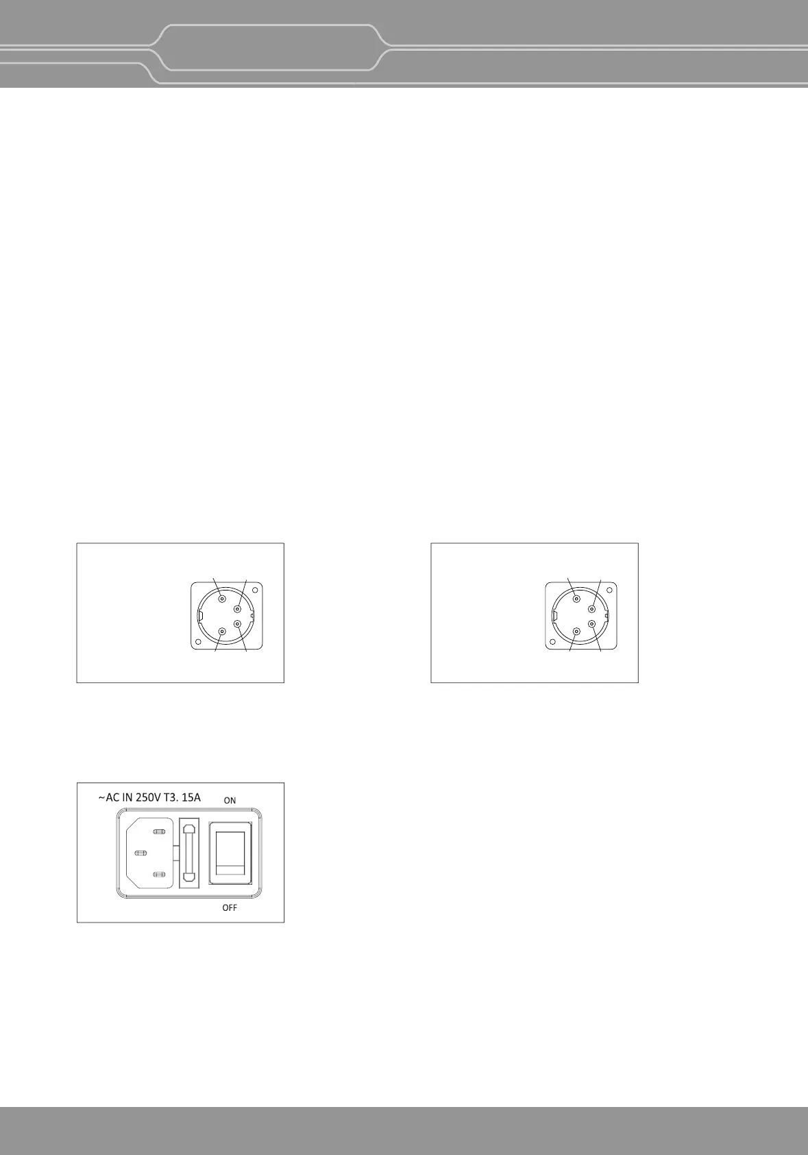
J : AC IN terminal
AC power input connector.
Connects the provided AC power cord.
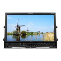
DC IN Socket
1 : GND
4 : +24V
4
12
3
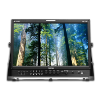
DC IN Socket
1 : GND
4 : +12V
4
12
3
OBM-U170/U171
OBM-U240/U241/U310/U311/X241/X310
OBM-U/X Series
4K LCD Professional Monitor
with 12G-SDI, Quad Link 4K
11
 Loading...