5.19.1 Cable lengths
Bus/sensor lines do not have mains voltage, but small protective voltage. They
must not be installed in parallel with mains lines ( induced signals). Shielded ca-
bles have to be installed if this is unavoidable.
Permissible cable lengths for all bus sensors:
-
Cu-cable up to 20m: 0,8 mm
2
-
Cu-cable up to 80m: 1 mm
2
-
Cu-cable up to 120m: 1,5 mm
2
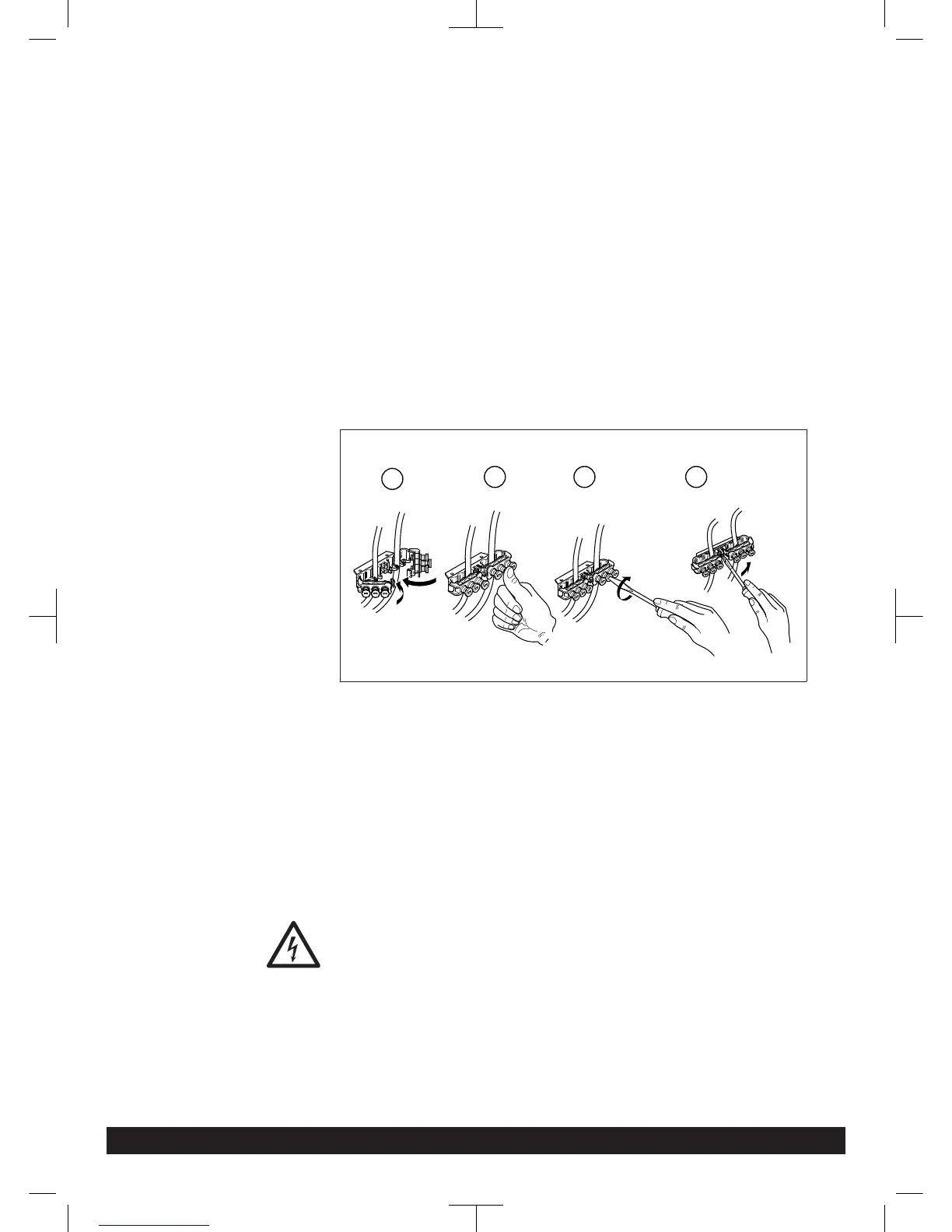
5.19.2 Strain relief fittings
All cables must be routed through the cable entries supplied and inserted through
the holes in the boiler base and then secured. Also secure cables by means of the
strain relief fittings on the control panel and then connect in accordance with the
wiring diagram ( Fig. 10 ).
Fig. 10: Strain relief
5.19.3
IP rating IPx4D
Tighten the cable entries to comply with the IPx4D rating and to safeguard the
specified air-tight sealing of the air chamber, so that the grommets tighten around
the cables.
5.19.4
Circulating pumps
The permissible current load per pump output is I
N max
= 1A.
5.19.5
Fuses
Device fuse in the control unit:
- F1 - T 6,3 H 250 ; mains
5.19.6
Connection sensor / components
Danger of electric shock!
The wiring diagram must be followed! Optional accessories must be fitted and
connected according to the instructions provided. Ensure earthing is correct.
Outdoor temperature sensor (included in delivery)
The outdoor temperature sensor is located in the accessory box. Follow pictorials
on box for installation instructions.
Installation
7308272-03 03.14 Paramount three 30-115 kW 37