8.10 Heating circuits
Comfort setpoint
(710, 1010, 1310)
Setting the maximum comfort setpoint in the heating phases. Without room sen-
sor or with the room influence (prog.no. 750, 1050, 1350), this value is used for
calculation of the flow temperature, to theoretically reach the set room tempera-
ture.
Reduced setpoint
(712, 1012, 1312)
Setting of the desired room temperature during the reduced heating phase. With-
out room sensor or with the room influence (prog.no. 750, 1050, 1350), this value
is used for calculation of the flow temperature, to theoretically reach the set
room temperature.
Frost protection setpoint
(714, 1014, 1314)
Setting of the desired room temperature during the frost protection operation.
Without room sensor or with the room influence (prog.no. 750, 1050, 1350), this
value is used for calculation of the flow temperature, to theoretically reach the
set room temperature. The heating circuit remains turned off until the flow tem-
perature drops so far that the room temperature falls below the frost protection
temperature.
Heating curve slope
(720, 1020, 1320)
Using the heating curve, the flow temperature setpoint is formed, which is used
for control of the heating circuit, based on the outside temperature. The slope of
the curve indicates by how much the flow temperature changes with changing
outside temperature.
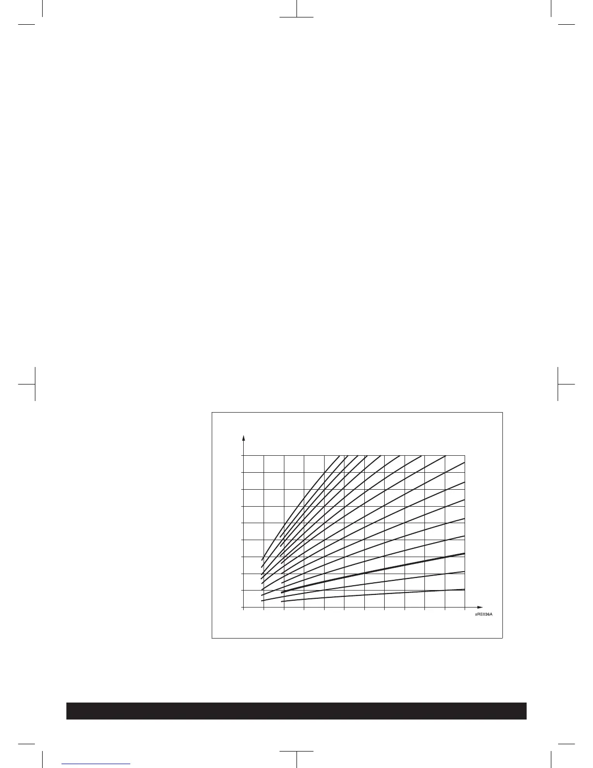
Determination of the heating curve slope
Enter lowest calculated outside temperature according to climate zone (e.g. -1°C in
London) into the diagram (see Fig. 13 ) (e.g. vertical line at -1°C). Enter the maxi-
mum flow temperature of the heating circuit, which is reached by calculating with
-1°C outside temperature at 20°C room temperature e.g., horizontal line at 82°C).
The intersecting point gives the value for the heating curve slope.
Fig. 13:
Heating curve diagram