POWER ELECTRONICS
VS65
INSTALLATION AND CONNECTION
17
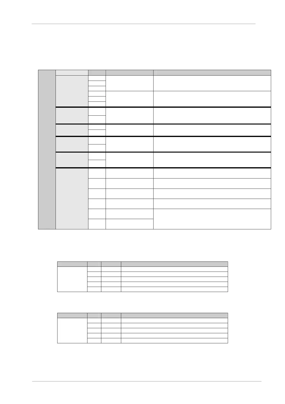
2.5. Control Terminals Description
Descriptions about the terminals on the Control board and the power supply.
PIN SIGNAL DESCRIPTION
L1
L2
L3
AC power input terminal To 3-phase AC power supply via module case circuit-breaker (MCCB).
U
V
MAIN LOOP
W
Soft starter’s output
terminal
To 3-phase asynchronous motor.
J10-13
CONTROL
POWER
SUPPLY
J10-14
AC control power supply’s
input terminal
To 110VAC 50Hz or 220VAC 50Hz.
J11-1
FAULT
RELAY
J11-2
Fault relay’s output
terminal
Closed in case of fault
Capacity: AC 220V 5A.
J11-3
BYPASS
CONTACTOR
J11-4
Bypass contactor’s control
terminal
Closed as startup is finished
Capacity: AC 220V 5A.
J11-5
INTERLOCK
RELAY
J11-6
Interlocking relay’s output
terminal
Closed status is controlled by programming
Capacity: AC 220V 5A.
J2-4
Emergency stop control
terminal
Checking the protector’s fault for Emergency stop
J2-3
RUN remote control
starting terminal
Remote RUN
J2-2
STOP remote control stop
terminal
Remote STOP
J2-1
COM remote common
terminal
Remote common terminal
J9-1
Current signal output
terminal CUT+
CONTROL CONNECTORS
INPUT AND
OUTPUTS
J9-2
Current signal output
terminal CUT
4-20mA chosen by programming. See 4.3.9
Depending on different field buses chosen by the user, terminal J6 can have different meanings, as
shown in the table below:
Profibus Communication Network:
CONNECTOR PIN SIGNAL DESCRIPTION
J6-1 GND Power ground terminal
J6-2 A Input signal
J6-3 RST Relay input
J6-4 B Inverse signal input
PROFIBUS
J6-5 5V Positive power source to be connected with matched resistance
Modbus Communication Network:
CONNECTOR PIN SIGNAL DESCRIPTION
J6-1 GND Power ground terminal
J6-2 A Input signal
J6-3 NC Not Connected
J6-4 B Inverse signal input
MODBUS
J6-5 5V Positive power source
Note: Matched resistance < 200 ohm