POWER ELECTRONICS
VS65
INSTALLATION AND CONNECTION
19
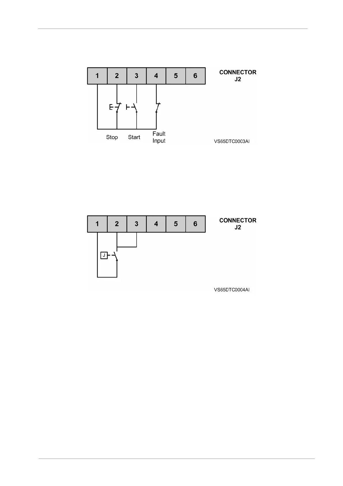
Figure 2.2 J2 Connector wiring
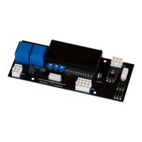
But the two-wire connection should be practiced for the cases below (See Fig 2.3).
1. When the customer needs only a switching contact to control starting and stop of softstarter,
like the control contact J of PC/PLC.
2. When the delay function of soft starter is used, when J is closed and after a certain delay, the
starter begins starting. The delay value can be set by programming (See 4.3.3 for details).
Figure 2.3 J2 Connector wiring
Analogue current signal output (4~20mA)
This is used to the proportional 4~20mA current signal of main loop, with the proportional
output current can be selected by programming (See 4.3.9).
Operational power supply terminal
Provides power supply 110~220V (AC 50Hz) by a voltage transformer usually.
Field bus terminal
MODBUS RTU and PROFIBUS share the terminal. It is necessary to select the protocol
while ordering the softstarter. See Chapter 7 for the communication protocol.