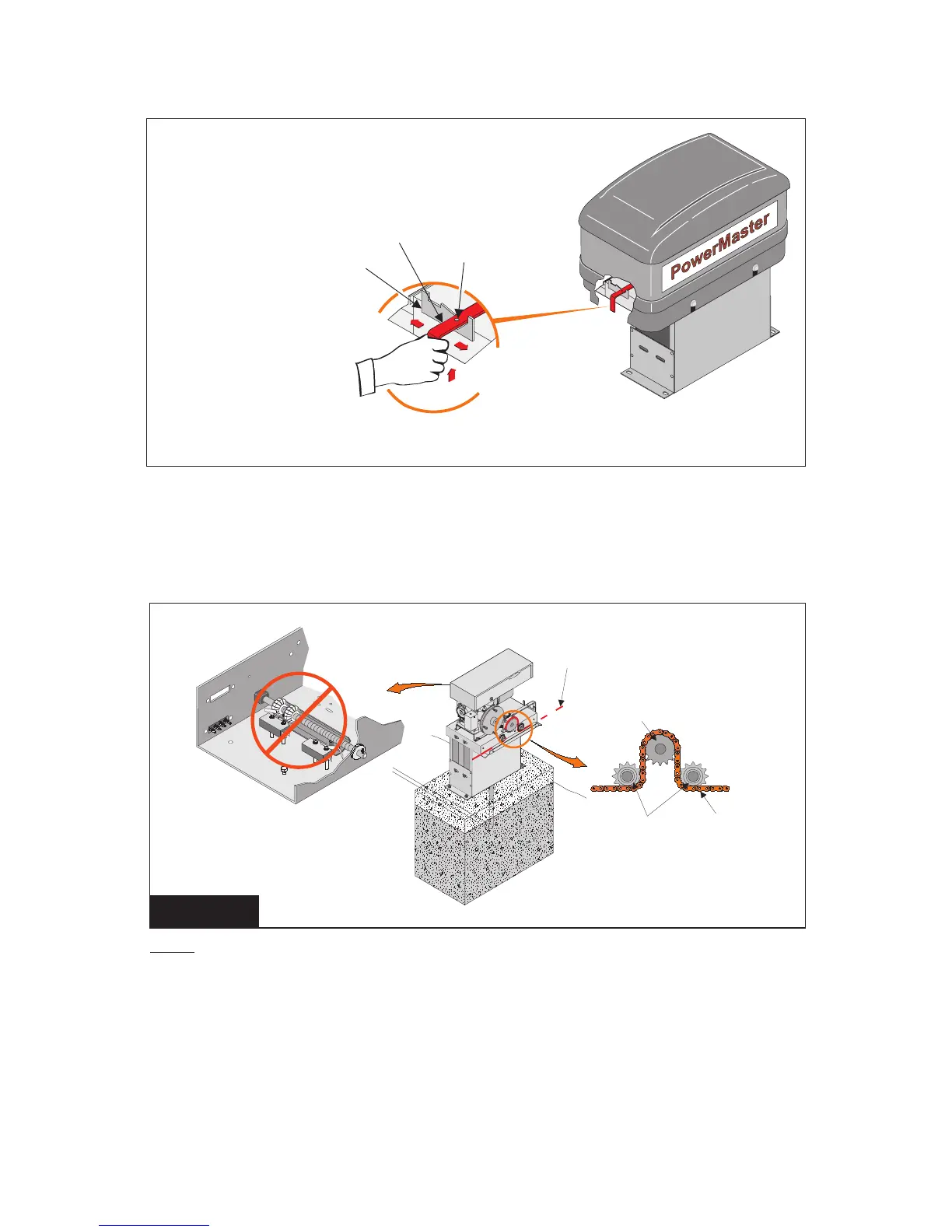
5. Disengage operator by moving the red disconnect lever (Located on the operator base
at the opposite end from the motor) to the disconnect position, and latch in place.
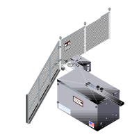
6. Thread free end of chain under rst idler sprocket, up and over drive sprocket, then
under the second idler sprocket. See Figure 6.
NOTE: When pulling chain through operator sprockets, the limit nuts in the electric box can be driven
passed their normal position. Reset limit nuts as necessary to prevent them from being damaged
during this procedure.
FIGURE 6
Disconnect
Lever
Padlock
Option Hole
Retaining
Bracket
To Disconnect Drive:
Move lever to the left until it
latches in retaining bracket.
To Re-Engage Drive:
Lift lever to unlatch,
then move lever to
the right.
7. Pull the chain through to the opposite end of the gate. Cut the chain to the correct
length, attach remaining chain take-up bolt and install in the gate bracket, as in Steps 2
through 4.
8. Adjust the gate bracket height at both ends of the gate to ensure the drive chain aligns
with the operator idler sprockets.
Drive Chain
Drive
Chain
Idler
Sprockets
Drive Sprocket