Page 11 of 19
PowerMate
®
L1/L2 Series Model
Repair Manual
Section H: Override Bearing Assembly
PROCEDURE:
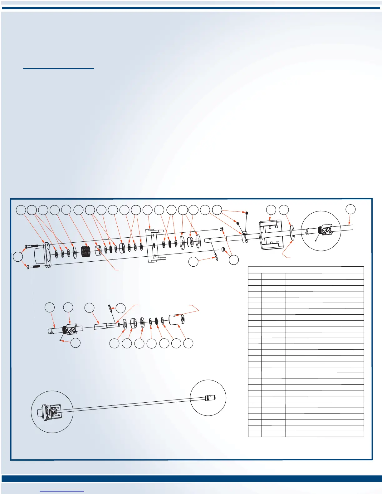
NOTE: Read all instructions carefully before attempting to make repairs to any part of the drive screw assembly. Refer
to the Screw Assembly Drawing.
1. Remove the brake assembly as outlined in the Brake Assembly procedure.
2. Continue the disassembly by removing the two steel thrust washers(11), steel thrust bearing(9), two plate
washers(13), and the urethane bumper(14).
3. As per the screw assembly drawing, replace the override bearing components (Bearing Override Kit P/N 400160)
in reverse order as follows: Items: 13-14-13-11-9-11-12
Apply a few drops of light machine oil to thrust bearing(9) and the roller bearing in the bearing retainer(12).
4. Replace the brake assembly components as per the Brake Assembly instruction.
DETAIL A
DETAIL C
DETAIL B
1 110450
BRAKE CAP L-SERIES
2 050840
WASHER THRUST BRONZE .060
3 050140
WASHER THRUST STEEL 1/2".090
4 150940
WASHER RETAINER
5
050800 BRAKE SPRING
6 050820 WASHER TOP BRAKE DRIVE
7
051680 ROLL PIN 3/16"
8 050810 WASHER THRUST STEEL 1/2"x .030
9 050120 BEARING T
HRUST STE
EL
10 050850 WASHER BOTTOM BRAKE DRIVE
11 050920 WASHER THRUST STEEL 1/2"x .060
12 310070
BEARING RETAINER ASSEMBLY
13 050040
PLATE WASHER 5/8"
14 100700 URETHANE BUMPER
15 052090
BALLNUT LOCKNUT 5/8"SCREW
16 050550
SET SCREW 1/4-20NC x 5/16
17 310250
BALLNUT BRACKET
18 050830
WASHER DISC SPRING 5/8"
19 050170
BALLNUT 5/8"
20 102040
DRIVE SCREW 5/8"
21 051850
WASHER 5/8"
22 300840
COUPLI
NG
23 050640
BOLT 1/4-20NC x 1 1/2"
24 050610
LOCK N
UT 1/4-20NC
25 055640 PLATE
WASHER 1/2"
26
050171 LOAD LOCKING SPRING
27 102045 LOAD LOCK PIN
PARTS LIST
ITEM PART
No.
DESCRIPTION
B
C
A
Pin Brake Washer(6) to Drive
Screw(20) with Roll Pin(7).
Pin Coupling(22) to Drive
Screw(20) with Roll Pin(7).
Note: Concave side towards
Ballnut Bracket.
SCREW ASSEMBLY L-1, LE-1
P/N 310010
24
13
17
14
18
16
15
16
24
11
8
4
5
9
3
23
1
22
6
8
10
2
2
12
1111
13
7
9
20
19
26
27
7
8
22
9
8
14
21
25
20
23
 Loading...