Page 16 of 19
PowerMate
®
L1/L2 Series Model
Repair Manual
Section K: Brake Assembly Replacement
PROCEDURE:
NOTE: Read all instructions carefully before attempting to make repairs to any part of the drive screw assembly.
Refer to the Screw Assembly Drawing on page 11.
1. With reference to the Screw Assembly drawing, remove the two ¼” bolts(23) and nuts(24). Proceed to remove the
brake cap(1), two bronze thrust washers(2), steel washer(3), washer retainer(4) and brake spring(5).
2. Drive out the 3/16” roll pin(7) taking care not to bend the screw shaft. Place a suitable support underneath the
brake drive top washer(6) for this operation.
3. Remove the brake drive top washer(6), two steel thrust washers(8), thrust washer(9), brake drive bottom
washer(10), two bronze thrust washers(2), and the steel thrust washers(11).
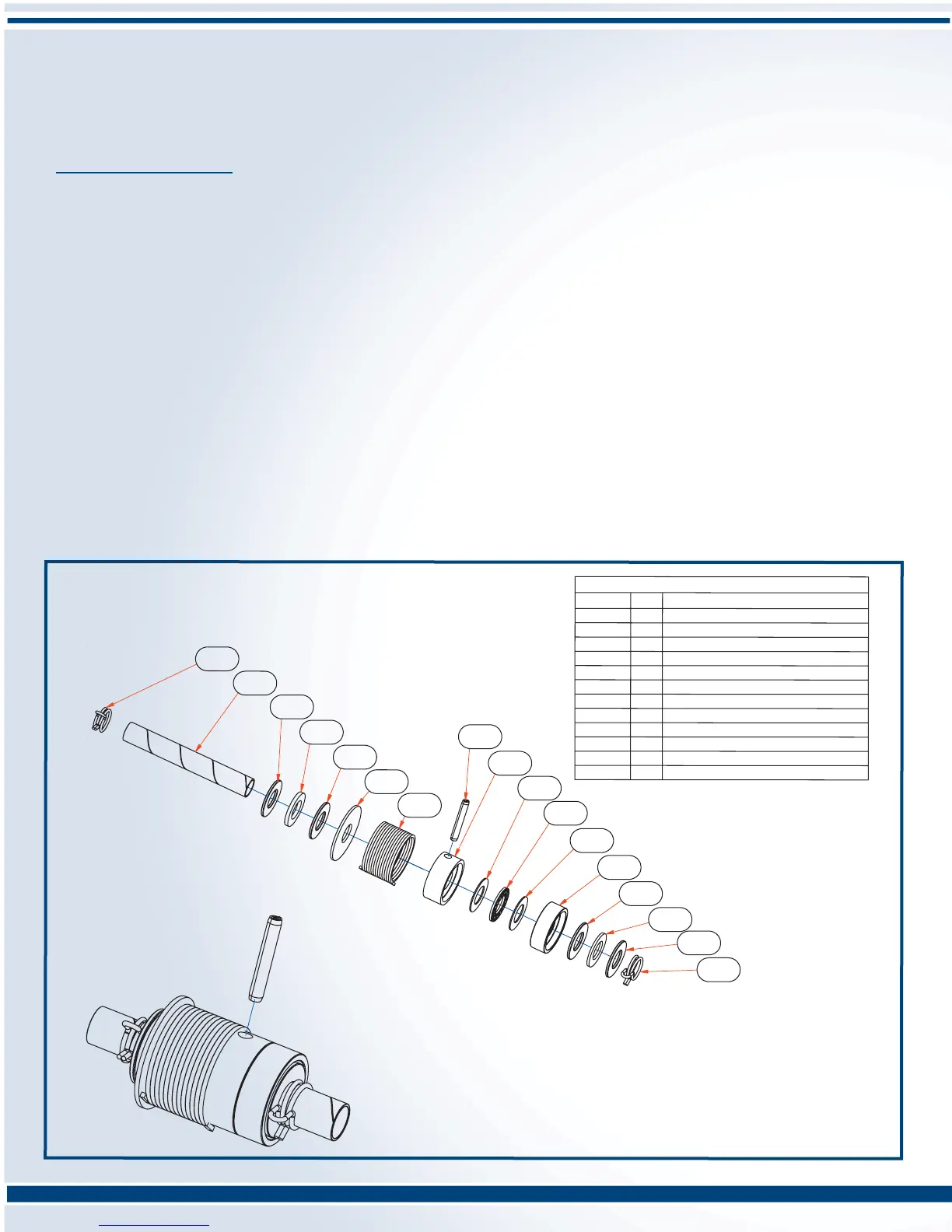
4. As per the screw assembly drawing, replace the brake assembly components (Brake Assembly Kit P/N 400150) in
reverse order as follows: (see drawing below)
Items: 2-11-2-10-8-9-8-6-7-5-4-2-3-2
During assembly, place a few drops of light machine oil on the thrust bearing(9) only. Remember to support the
brake drive top washer(6) when installing the 3/16” roll pin(17).
5. Install brake cap(1) and insert the ¼” bolts(22) and fasten with the nuts(23).
050120 1
BEARING THRUST STEEL
050140 1
WASHER THRUST STEEL 1/2".090
050800 1 BRAKE SPRING
050810 2
WASHER THRUST STEEL 1/2"x .030
050820 1
WASHER TOP BRAKE DRIVE
050840 4
WASHER THRUST BRONZE .060
050850 1
WASHER BOTTOM BRAKE DRIVE
050920 1 WASHER THRUST STEEL 1/2"x .060
051680 1
ROLL PIN SPIROL 3/16"x 1 1/8"
150940 1 WASHER RETAINER
050174 1
BALLNUT ARBOR
050175 2
SPRING CLIP - ARBOR
PARTS LIST
PART No.
QTY DESCRIPTION
050175
050174
050840
050140
050840
150940
050800
051680
050820
050810
050810
050850
050840
050920
050840
050175
050120
 Loading...