Page 17 of 19
PowerMate
®
L1/L2 Series Model
Repair Manual
Section L: Ballnut Locknut Adjustment
PROCEDURE:
1. Place the PowerMate on a suitable work bench with the machine resting on it’s wheels and rear handles (toeplate
up). Activate the unit until it is extended approximately half-way. Remove the fuse.
2. Loosen the two Set Screws 5/16” (Item 16) on the Ballnut Locknut (Item 15). (See Pic L - A)
(refer to screw assembly drawing on pg 11)
3. With a screwdriver against one of the three fl at sides of the Ballnut (Item 19), hand tighten the Ballnut Locknut (item
15). Tighten the two Set Screws 5/16” (Item 16). (See Pic L - B)
4. Re-install Fuse and test. (See Pic L - C)
Note: Ballnut must spin in the ballnut bracket when machine is operated to its limit in either direction. Re-adjust the
ballnut locknut (Item 15) 1/4 turn if necessary.
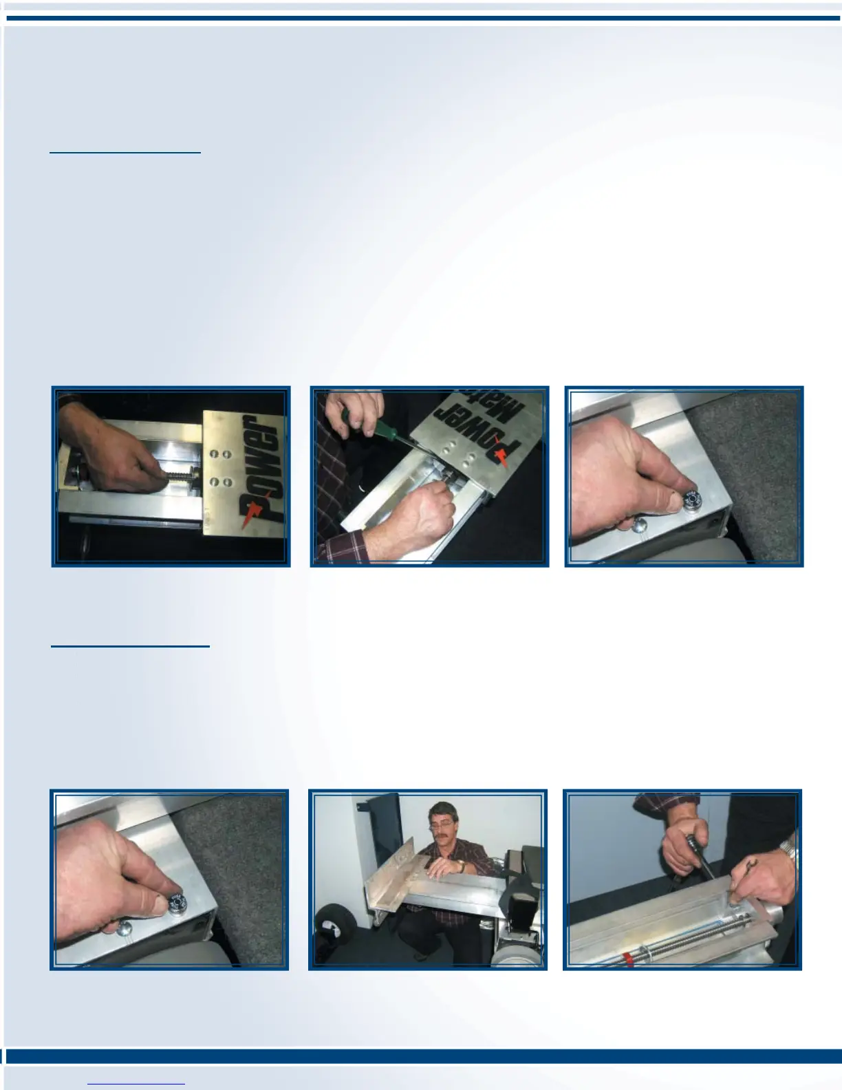
Pic L - A: Loosen the two set screws
Pic L - B: Hand tighten the Ballnut
Locknut
Pic L - C: Re-install Fuse and test
Section M: Ballnut Bracket Replacement
PROCEDURE:
1. Place the PowerMate on a suitable work bench with the machine resting on it’s wheels and rear handles (toeplate
up). Activate the unit until it is extended approximately half-way. Remove the fuse. (See Pic M - A on pg 17)
2. Remove four nuts retaining the toeplate to the Outer Frame. (See Pic M - B on pg 17) Remove the two bolts and
nuts fastening the Bearing Retainer and the Inner Frame. (See Pic M - C on pg 17) The Outer Frame can now be
slid off the Inner Frame in the direction of the handles.
Pic M - A: Remove Fuse
Pic M - B: Remove four nuts retaining
the toeplate to the outer frame.
Pic M - C: Remove the tow bolts and
nuts fastening the bearing retainer.
 Loading...