Page 7 of 19
PowerMate
®
L1/L2 Series Model
Repair Manual
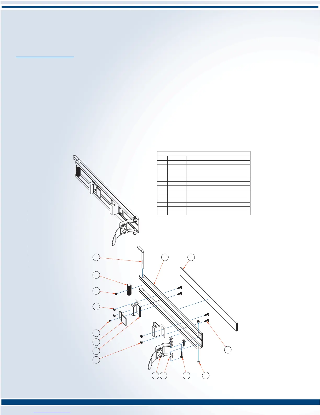
1 110130
STRAP BAR ALUMINUM
2 050740
BOLT 1/4-20 x 7/8 CARRIAGE ZINC
3 101960 FELT STRAP BAR 1/4"x 2"x 23"
4 302110
CAM HANDLE
5
310040 CAM
6 050990
SCREW HEXSOC SET 5/16-18 x 5/16
7 050610
NUT 1/4-20 RING LOCK ZINC
8 050570
SCREW SELF TAPPING #10 x 3/8"
9 110540
STRAPPING 3"PIECE
10 110020 STRAPBAR CONNECTOR LS
11 310530
STRAP 10' c/w TOGGLE
12 050070 WASHER PLATE 1/4 ZINC
13 050580
SCREW PAN HD SLOT 1/4-20x1 1/4
PARTS LIST
ITEM PART No.
DESCRIPTION
STRAP BAR ASSEMBLY
PN 410020S
4
5
6
7
8
9
10
7
11 12 13
7
2
31
PROCEDURE:
1. Remove the two Screw Pan HD Slot (Item 13), 3 Washer Plates (Item 12), 2 Nuts 1/4-20 Ring Lock (Item 7),
Strap & Toggle (Item 11) with slot screwdriver and 7/16” wrench. Discard.
2. Position new Strap & Toggle with three Washer Plates (Item 12) positioned inside of the Strap-bar, two on the
inside top, one on the inside bottom. Insert the two Screw Pan HD Slot (Item 13) and affi x with two Nuts 1/4-20
Ring Lock (Item 7). Snug, but do not over tighten.
Offset Cam Adjustment
PROCEDURE:
1. Move Cam Handle (Item 4) parallel to the Strap Bar (Item 1).
2. Raise the Cam Handle (Item 4) and move the Cam (Item 5) and Screw Hexsoc Set 5/16” (Item 6) 90° to the Cam
Handle.
3. Tighten with 5/32” allen key.
Section D: Strap Replacement
 Loading...